Toyota CH-R Service Manual: Adjustment
ADJUSTMENT
PROCEDURE
1. INSPECT AND ADJUST BRAKE PEDAL HEIGHT
(a) Remove the No. 1 air duct.
Click here
.gif)
(b) Check the brake pedal height.
NOTICE:
- Inspect and adjust the brake pedal height with the floor carpet folded back.
- When performing the measurement, make sure that the measuring device is contacting the surface of the dash panel insulator assembly clip.
(1) Measure the shortest distance between the brake pedal pad surface and dash panel insulator assembly clip.

|
*1 |
Brake Pedal Pad |
*2 |
Dash Panel Insulator Assembly Clip |
|
*a |
Brake Pedal Height |
- |
- |
Brake Pedal Height from Dash Panel Insulator Assembly Clip:
176.0 to 188.0 mm (6.93 to 7.40 in.)
If the pedal height is not as specified, adjust the brake pedal height according to the procedure below.
(c) Adjust the brake pedal height.
|
(1) Remove the stop light switch assembly. Click here
|
|
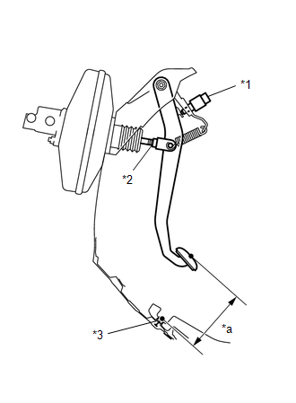
(2) Loosen the clevis lock nut.
(3) Adjust the brake pedal height by turning the push rod.
Brake Pedal Height from Dash Panel Insulator Assembly Clip:
176.0 to 188.0 mm (6.93 to 7.40 in.)
(4) Tighten the clevis lock nut.
Torque:
22 N·m {224 kgf·cm, 16 ft·lbf}
(5) Install the stop light switch assembly.
Click here
(d) Install the No. 1 air duct.
Click here
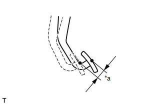
2. INSPECT BRAKE PEDAL FREE PLAY
|
(a) Depress the brake pedal until a slight resistance is felt. Measure the brake pedal free play as shown in the illustration. Brake Pedal Free Play: 1.0 to 6.0 mm (0.0394 to 0.236 in.) If the pedal free play is not as specified, check the stop light switch clearance. Click here
If the pedal free play is as specified, proceed to the Inspect Brake Pedal Reserve Distance procedure. |
|
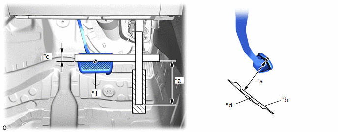
3. INSPECT BRAKE PEDAL RESERVE DISTANCE
(a) With the engine running, depress the brake pedal and measure the brake pedal reserve distance.
|
*1 |
Brake Pedal Pad |
- |
- |
|
*a |
Brake Pedal Reserve Distance |
*b |
Floor Panel |
|
*c |
30 mm (1.18 in.) |
*d |
Line Extended from Floor Panel Surface |
Brake Pedal Reserve Distance from Line Extended from Floor Panel Surface at 300 N (31 kgf, 67.4 lbf):
115.0 mm (4.53 in.) or more
If the distance is not as specified, troubleshoot the brake system.
Click here
 Removal
REMOVAL
CAUTION / NOTICE / HINT
The necessary procedures (adjustment, calibration, initialization, or registration)
that must be performed after parts are removed, installed, or replaced during th ...
 Installation
INSTALLATION
PROCEDURE
1. INSTALL BRAKE PEDAL PAD
(a) Install the brake pedal pad from the brake pedal support assembly.
2. INSTALL BRAKE PEDAL SUPPORT ASSEMBLY
(a) Install the nut to the brake p ...
Other materials:
Toyota CH-R Service Manual > Front Evaporator Temperature Sensor(for Denso Made): Components
COMPONENTS
ILLUSTRATION
*1
AIR CONDITIONING HARNESS ASSEMBLY
*2
COOLER EXPANSION VALVE
*3
HEATER CLAMP
*4
HEATER PIPE GROMMET
*5
HEATER RADIATOR UNIT SUB-ASSEMBLY
...
Toyota CH-R Service Manual > Continuously Variable Transaxle Assembly(when Not Using The Engine Support Bridge): Components
COMPONENTS
ILLUSTRATION
*1
ENGINE WIRE
*2
FRONT SUSPENSION CROSSMEMBER SUB-ASSEMBLY
*3
NO. 2 ENGINE MOVING CONTROL ROD
*4
NO. 3 WATER BY-PASS HOSE
*5
NO. 5 WATER BY-PASS HOSE ...
Toyota C-HR (AX20) 2023-2026 Owner's Manual
Toyota CH-R Owners Manual
- For safety and security
- Instrument cluster
- Operation of each component
- Driving
- Interior features
- Maintenance and care
- When trouble arises
- Vehicle specifications
- For owners
Toyota CH-R Service Manual
- Introduction
- Maintenance
- Audio / Video
- Cellular Communication
- Navigation / Multi Info Display
- Park Assist / Monitoring
- Brake (front)
- Brake (rear)
- Brake Control / Dynamic Control Systems
- Brake System (other)
- Parking Brake
- Axle And Differential
- Drive Shaft / Propeller Shaft
- K114 Cvt
- 3zr-fae Battery / Charging
- Networking
- Power Distribution
- Power Assist Systems
- Steering Column
- Steering Gear / Linkage
- Alignment / Handling Diagnosis
- Front Suspension
- Rear Suspension
- Tire / Wheel
- Tire Pressure Monitoring
- Door / Hatch
- Exterior Panels / Trim
- Horn
- Lighting (ext)
- Mirror (ext)
- Window / Glass
- Wiper / Washer
- Door Lock
- Heating / Air Conditioning
- Interior Panels / Trim
- Lighting (int)
- Meter / Gauge / Display
- Mirror (int)
- Power Outlets (int)
- Pre-collision
- Seat
- Seat Belt
- Supplemental Restraint Systems
- Theft Deterrent / Keyless Entry

0.0128