Toyota CH-R Service Manual: Removal
REMOVAL
CAUTION / NOTICE / HINT
The necessary procedures (adjustment, calibration, initialization, or registration) that must be performed after parts are removed, installed, or replaced during the brake pedal support assembly removal/installation are shown below.
Necessary Procedures After Parts Removed/Installed/Replaced|
Replacement Part or Procedure |
Necessary Procedure |
Effect/Inoperative when not Performed |
Link |
|---|---|---|---|
|
Disconnect cable from negative battery terminal |
Initialize back door lock |
Power door lock control system |
|
CAUTION:
Some of these service operations affect the SRS airbag system. Read the precautionary notices concerning the SRS airbag system before servicing.
.png)
Click here
.gif)
PROCEDURE
1. REMOVE INSTRUMENT PANEL SAFETY PAD SUB-ASSEMBLY
Click here
2. REMOVE STOP LIGHT SWITCH ASSEMBLY
Click here
3. REMOVE STOP LIGHT SWITCH MOUNTING ADJUSTER
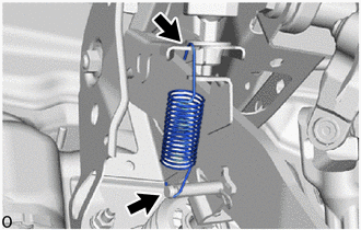
4. REMOVE BRAKE PEDAL RETURN SPRING
|
(a) Remove the brake pedal return spring from the brake pedal support assembly and push rod pin. |
|
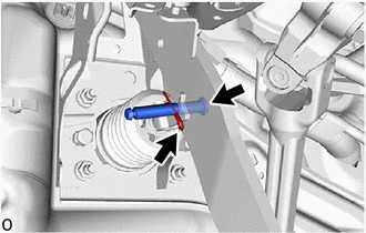
5. REMOVE PUSH ROD PIN
|
(a) Remove the clip and push rod pin to separate the brake pedal support assembly from the brake master cylinder push rod clevis. |
|
6. REMOVE BRAKE PEDAL SUPPORT ASSEMBLY
|
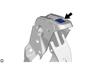
(a) Disconnect the brake pedal load sensing switch connector. |
|
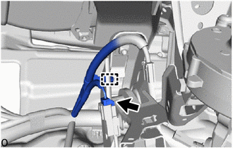
(b) Disengage the clamp to separate the wire harness from the brake pedal support assembly.
|
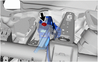
(c) Remove the bolt and separate the brake pedal support assembly from the instrument panel reinforcement assembly. |
|
|
(d) Remove the 2 clips. |
|
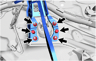
(e) Remove the 4 nuts and brake pedal support assembly.
|
(f) Remove the nut from the brake pedal support assembly. |
|
7. REMOVE BRAKE PEDAL PAD
(a) Remove the brake pedal pad from the brake pedal support assembly.
 Components
COMPONENTS
ILLUSTRATION
*1
BRAKE PEDAL PAD
*2
BRAKE PEDAL RETURN SPRING
*3
BRAKE PEDAL SUPPORT ASSEMBLY
*4
...
 Adjustment
ADJUSTMENT
PROCEDURE
1. INSPECT AND ADJUST BRAKE PEDAL HEIGHT
(a) Remove the No. 1 air duct.
Click here
(b) Check the brake pedal height.
NOTICE:
Inspect and adjust the brake pedal ...
Other materials:
Toyota CH-R Service Manual > Hood: Adjustment
ADJUSTMENT
CAUTION / NOTICE / HINT
*a
Centering Bolt
*b
Standard Bolt
HINT:
Centering bolts are used to install the hood hinges and hood lock. The
hood and hood lock cannot be adjusted with the centering bolts installed.
...
Toyota CH-R Service Manual > Rear Door Outside Moulding: Components
COMPONENTS
ILLUSTRATION
*1
REAR DOOR OUTSIDE MOULDING
*2
HOLE COVER
*3
GASKET
-
-
ILLUSTRATION
*1
NO. 2 OUTSIDE MOULDING RETAINER
*2
REAR DOOR UP ...
Toyota C-HR (AX20) 2023-2026 Owner's Manual
Toyota CH-R Owners Manual
- For safety and security
- Instrument cluster
- Operation of each component
- Driving
- Interior features
- Maintenance and care
- When trouble arises
- Vehicle specifications
- For owners
Toyota CH-R Service Manual
- Introduction
- Maintenance
- Audio / Video
- Cellular Communication
- Navigation / Multi Info Display
- Park Assist / Monitoring
- Brake (front)
- Brake (rear)
- Brake Control / Dynamic Control Systems
- Brake System (other)
- Parking Brake
- Axle And Differential
- Drive Shaft / Propeller Shaft
- K114 Cvt
- 3zr-fae Battery / Charging
- Networking
- Power Distribution
- Power Assist Systems
- Steering Column
- Steering Gear / Linkage
- Alignment / Handling Diagnosis
- Front Suspension
- Rear Suspension
- Tire / Wheel
- Tire Pressure Monitoring
- Door / Hatch
- Exterior Panels / Trim
- Horn
- Lighting (ext)
- Mirror (ext)
- Window / Glass
- Wiper / Washer
- Door Lock
- Heating / Air Conditioning
- Interior Panels / Trim
- Lighting (int)
- Meter / Gauge / Display
- Mirror (int)
- Power Outlets (int)
- Pre-collision
- Seat
- Seat Belt
- Supplemental Restraint Systems
- Theft Deterrent / Keyless Entry

0.0067