Toyota CH-R Service Manual: Reassembly
REASSEMBLY
PROCEDURE
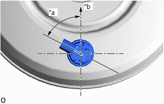
1. INSTALL VACUUM WARNING SWITCH ASSEMBLY
(a) Install a new check valve grommet to the brake booster assembly.
|
(b) Install the vacuum sensor assembly to the brake booster assembly as shown in the illustration. |
|
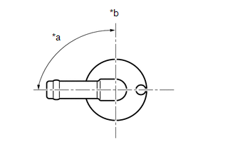
2. INSTALL BRAKE VACUUM CHECK VALVE ASSEMBLY
(a) Install a new check valve grommet to the brake booster assembly.
|
(b) Install the brake vacuum check valve assembly to the brake booster assembly as shown in the illustration. |
|
 Inspection
INSPECTION
PROCEDURE
1. INSPECT BRAKE VACUUM CHECK VALVE ASSEMBLY
(a) Check that there is ventilation from the booster to the engine, and
no ventilation from the engine to the booste ...
 Installation
INSTALLATION
PROCEDURE
1. INSTALL BRAKE BOOSTER GASKET
(a) Install a new brake booster gasket to the brake booster assembly.
2. INSTALL BRAKE BOOSTER ASSEMBLY
(a) Temporarily install the brake bo ...
Other materials:
Toyota CH-R Service Manual > Vehicle Stability Control System: Acceleration Sensor Internal Circuit (C1419,C1435)
DESCRIPTION
These DTCs are stored when the skid control ECU (brake actuator assembly) receives
an internal malfunction signal from the yaw rate and acceleration sensor (airbag
sensor assembly).
DTC No.
Detection Item
DTC Detection Condition
Trouble A ...
Toyota CH-R Service Manual > Power Window Control System: Power Window Switch Malfunction (B2312)
DESCRIPTION
The power window regulator motor assemblies are operated by the multiplex network
master switch assembly, power window regulator switch assembly or rear power window
regulator switch assemblies. The power window regulator motor assemblies have motor,
regulator and ECU functions.
...
Toyota C-HR (AX20) 2023-2026 Owner's Manual
Toyota CH-R Owners Manual
- For safety and security
- Instrument cluster
- Operation of each component
- Driving
- Interior features
- Maintenance and care
- When trouble arises
- Vehicle specifications
- For owners
Toyota CH-R Service Manual
- Introduction
- Maintenance
- Audio / Video
- Cellular Communication
- Navigation / Multi Info Display
- Park Assist / Monitoring
- Brake (front)
- Brake (rear)
- Brake Control / Dynamic Control Systems
- Brake System (other)
- Parking Brake
- Axle And Differential
- Drive Shaft / Propeller Shaft
- K114 Cvt
- 3zr-fae Battery / Charging
- Networking
- Power Distribution
- Power Assist Systems
- Steering Column
- Steering Gear / Linkage
- Alignment / Handling Diagnosis
- Front Suspension
- Rear Suspension
- Tire / Wheel
- Tire Pressure Monitoring
- Door / Hatch
- Exterior Panels / Trim
- Horn
- Lighting (ext)
- Mirror (ext)
- Window / Glass
- Wiper / Washer
- Door Lock
- Heating / Air Conditioning
- Interior Panels / Trim
- Lighting (int)
- Meter / Gauge / Display
- Mirror (int)
- Power Outlets (int)
- Pre-collision
- Seat
- Seat Belt
- Supplemental Restraint Systems
- Theft Deterrent / Keyless Entry

0.0104