Toyota CH-R Service Manual: Removal
REMOVAL
CAUTION / NOTICE / HINT
The necessary procedures (adjustment, calibration, initialization, or registration) that must be performed after parts are removed and installed, or replaced during front lower No. 1 suspension arm sub-assembly LH removal/installation are shown below.
Necessary Procedures After Parts Removed/Installed/Replaced|
Replaced Part or Performed Procedure |
Necessary Procedure |
Effect/Inoperative Function when Necessary Procedure not Performed |
Link |
|---|---|---|---|
|
Front wheel alignment adjustment |
|
|
|
|
Suspension, tires, etc. (The vehicle height changes because of suspension or tire replacement) |
Initialize No. 1 headlight ECU sub-assembly LH |
Automatic headlight beam level control system |
|
HINT:
- Use the same procedure for the RH side and LH side.
- The following procedure is for the LH side.
PROCEDURE
1. REMOVE FRONT WHEEL
Click here
.gif)
2. REMOVE NO. 1 ENGINE UNDER COVER
Click here
3. REMOVE REAR ENGINE UNDER COVER LH
Click here
4. REMOVE FRONT LOWER NO. 1 SUSPENSION ARM SUB-ASSEMBLY
|
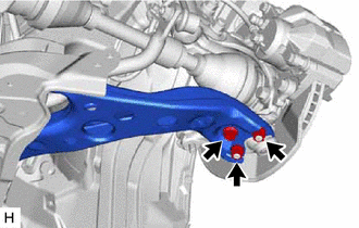
(a) Remove the bolt and 2 nuts and separate the front lower No. 1 suspension arm sub-assembly from the front lower ball joint assembly. |
|
|
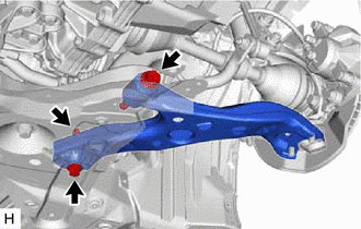
(b) Remove the 2 bolts, nut and front lower No. 1 suspension arm sub-assembly from the front suspension crossmember sub-assembly. NOTICE: Because the nut has its own stopper, do not turn the nut. Loosen the bolt with the nut secured. |
|
 Installation
INSTALLATION
PROCEDURE
1. INSTALL FRONT LOWER NO. 1 SUSPENSION ARM SUB-ASSEMBLY
(a) Temporarily install the front lower No. 1 suspension arm sub-assembly LH
to the front suspension crossmember su ...

Other materials:
Toyota CH-R Owners Manual > Driving procedures: Engine (ignition) switch (vehicles without a smart key system)
Starting the engine
Check that the parking brake is set.
Check that the shift lever is in P.
Firmly depress the brake pedal.
Turn the engine switch to the "START" position to start the engine.
Changing the engine switch positions
"LOCK"
The steering wheel is lo ...
Toyota CH-R Owners Manual > Adjusting the seats: Head restraints
Head restraints are provided for all seats.
Head restraints are provided for all seats.
Up
Pull the head restraints up.
Down
Push the head restraint down while pressing the lock release button.
Rear seats
■ Rear outboard seats
To fold
Pull the head restraint up while pressing ...
Toyota C-HR (AX20) 2023-2026 Owner's Manual
Toyota CH-R Owners Manual
- For safety and security
- Instrument cluster
- Operation of each component
- Driving
- Interior features
- Maintenance and care
- When trouble arises
- Vehicle specifications
- For owners
Toyota CH-R Service Manual
- Introduction
- Maintenance
- Audio / Video
- Cellular Communication
- Navigation / Multi Info Display
- Park Assist / Monitoring
- Brake (front)
- Brake (rear)
- Brake Control / Dynamic Control Systems
- Brake System (other)
- Parking Brake
- Axle And Differential
- Drive Shaft / Propeller Shaft
- K114 Cvt
- 3zr-fae Battery / Charging
- Networking
- Power Distribution
- Power Assist Systems
- Steering Column
- Steering Gear / Linkage
- Alignment / Handling Diagnosis
- Front Suspension
- Rear Suspension
- Tire / Wheel
- Tire Pressure Monitoring
- Door / Hatch
- Exterior Panels / Trim
- Horn
- Lighting (ext)
- Mirror (ext)
- Window / Glass
- Wiper / Washer
- Door Lock
- Heating / Air Conditioning
- Interior Panels / Trim
- Lighting (int)
- Meter / Gauge / Display
- Mirror (int)
- Power Outlets (int)
- Pre-collision
- Seat
- Seat Belt
- Supplemental Restraint Systems
- Theft Deterrent / Keyless Entry

0.0076