Toyota CH-R Service Manual: Installation
INSTALLATION
PROCEDURE
1. INSTALL FRONT LOWER NO. 1 SUSPENSION ARM SUB-ASSEMBLY
(a) Temporarily install the front lower No. 1 suspension arm sub-assembly LH to the front suspension crossmember sub-assembly with the 2 bolts and nut.
(b) Install the front lower No. 1 suspension arm sub-assembly LH to the front lower ball joint assembly LH with the bolt and 2 nuts.
Torque:
89 N·m {908 kgf·cm, 66 ft·lbf}
2. INSTALL FRONT WHEEL
Click here
.gif)
3. STABILIZE SUSPENSION
Click here
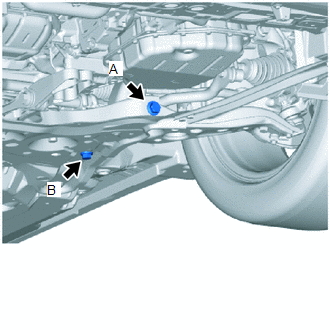
4. FULLY TIGHTEN FRONT LOWER NO. 1 SUSPENSION ARM SUB-ASSEMBLY
|
(a) Fully tighten the front lower No. 1 suspension arm sub-assembly with the 2 bolts. Torque: Bolt A : 240 N·m {2447 kgf·cm, 177 ft·lbf} Bolt B : 125 N·m {1275 kgf·cm, 92 ft·lbf} NOTICE: Because the nut has its own stopper, do not turn the nut. Tighten the bolt with the nut secured. |
|
5. INSTALL REAR ENGINE UNDER COVER LH
Click here
6. INSTALL NO. 1 ENGINE UNDER COVER
Click here
7. INSPECT AND ADJUST FRONT WHEEL ALIGNMENT
Click here
 Components
COMPONENTS
ILLUSTRATION
*1
NO. 1 ENGINE UNDER COVER
*2
REAR ENGINE UNDER COVER LH
N*m (kgf*cm, ft.*lbf): Specified torque
...
 Removal
REMOVAL
CAUTION / NOTICE / HINT
The necessary procedures (adjustment, calibration, initialization, or registration)
that must be performed after parts are removed and installed, or replaced during ...
Other materials:
Toyota CH-R Service Manual > Console Box Light: Installation
INSTALLATION
PROCEDURE
1. INSTALL INSTRUMENT CLUSTER FINISH PANEL CENTER GARNISH
(a) Engage the claws to install the instrument cluster finish panel center garnish
as shown in the illustration.
Install in this Direction
2. INSTALL INSTRUMENT CLUSTER FINISH PANEL ...
Toyota CH-R Service Manual > Tire Pressure Warning System: Transmitter ID1 Operation Stop (C2111/11-C2115/15)
DESCRIPTION
The tire pressure warning valve and transmitters that are installed in the tire
and wheel assemblies measure the tire pressures. The measured values are transmitted
to the tire pressure warning ECU and receiver in the vehicle as radio waves. The
ECU compares the measured tire pres ...
Toyota C-HR (AX20) 2023-2026 Owner's Manual
Toyota CH-R Owners Manual
- For safety and security
- Instrument cluster
- Operation of each component
- Driving
- Interior features
- Maintenance and care
- When trouble arises
- Vehicle specifications
- For owners
Toyota CH-R Service Manual
- Introduction
- Maintenance
- Audio / Video
- Cellular Communication
- Navigation / Multi Info Display
- Park Assist / Monitoring
- Brake (front)
- Brake (rear)
- Brake Control / Dynamic Control Systems
- Brake System (other)
- Parking Brake
- Axle And Differential
- Drive Shaft / Propeller Shaft
- K114 Cvt
- 3zr-fae Battery / Charging
- Networking
- Power Distribution
- Power Assist Systems
- Steering Column
- Steering Gear / Linkage
- Alignment / Handling Diagnosis
- Front Suspension
- Rear Suspension
- Tire / Wheel
- Tire Pressure Monitoring
- Door / Hatch
- Exterior Panels / Trim
- Horn
- Lighting (ext)
- Mirror (ext)
- Window / Glass
- Wiper / Washer
- Door Lock
- Heating / Air Conditioning
- Interior Panels / Trim
- Lighting (int)
- Meter / Gauge / Display
- Mirror (int)
- Power Outlets (int)
- Pre-collision
- Seat
- Seat Belt
- Supplemental Restraint Systems
- Theft Deterrent / Keyless Entry

0.0085