Toyota CH-R Service Manual: Terminals Of Ecu
TERMINALS OF ECU
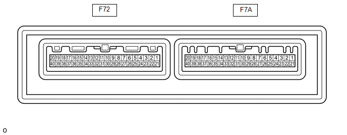
AIR CONDITIONING AMPLIFIER ASSEMBLY
HINT:
Check from the rear of the connector while it is connected to the air conditioning amplifier assembly.
|
Terminal No. (symbol) |
Wiring Color |
Terminal Description |
Condition |
Specified Condition |
|---|---|---|---|---|
|
F72-1 (B) - Body ground |
V - Body ground |
Power source (Back-up) |
Always |
11 to 14 V |
|
F72-3 (LIN1) - F72-29 (GND) |
L - W-B |
LIN communication signal (Air conditioning control assembly) |
Ignition switch ON |
Pulse generation (See waveform 1) |
|
F72-5 (IG+) - Body ground |
B - Body ground |
Power Source (IG) |
Ignition switch ON |
11 to 14 V |
|
Ignition switch off |
Below 1 V |
|||
|
F72-9 (CANH) - F72-10 (CANL) |
P - SB |
CAN communication |
CAN communication is performed |
Pulse generation |
|
F72-15 (SOL-) - F72-29 (GND) |
L - W-B |
Compressor solenoid operation |
|
Pulse generation (See waveform 2) |
|
F72-17 (NAIN) - F72-29 (GND)*1 |
W - W-B |
Input of status of ion generator sub-assembly |
|
3.5 to 5 V |
|
Below 2 V |
|||
|
F72-19 (PTC1) - F72-29 (GND)*2 |
L - W-B |
Output for driving PTC1 heater relay |
|
Below 1 V |
|
11 to 14 V |
|||
|
F72-20 (PTC3) - F72-29 (GND)*2 |
BR - W-B |
Output for driving PTC3 heater relay |
|
Below 1 V |
|
11 to 14 V |
|||
|
F72-29 (GND) - Body ground |
W-B - Body ground |
Ground for main power supply |
Always |
Below 1 V |
|
F72-30 (TR) - F72-31 (SG-1) |
B - LG |
Cooler thermistor (room temperature sensor) |
|
1.8 to 1.6 V |
|
1.0 to 0.8 V |
|||
|
F72-31 (SG-1) - Body ground |
LG - Body ground |
Ground for cooler thermistor (room temperature sensor) |
Always |
Below 1 V |
|
F72-32 (SG-2) - Body ground |
G - Body ground |
Ground for air conditioner pressure sensor |
Always |
Below 1 V |
|
F72-33 (PRE) - F72-32 (SG-2) |
V - G |
Input from refrigerant gas sensor |
|
4.61 V or higher |
|
Below 0.74 V |
|||
|
0.74 to 4.61 V |
|||
|
F72-34 (S5-3) - F72-32 (SG-2) |
GR - G |
Power supply for air conditioner pressure sensor |
Ignition switch ON |
4.75 to 5.25 V |
|
Ignition switch OFF |
Below 1 V |
|||
|
F72-37 (NANO) - F72-29 (GND)*1 |
R - W-B |
Output for driving ion generator sub-assembly |
|
3.5 to 5 V |
|
Below 2 V |
|||
|
F72-39 (PTC2) - F72-29 (GND)*2 |
V - W-B |
Output for driving PTC2 heater relay |
|
Below 1 V |
|
11 to 14 V |
|||
|
F7A-2 (B2AI) - Body ground |
- |
Output for driving the motor to switch inlet/outlet B2 |
|
Pulse generation (See waveform 3) |
|
F7A-3 (A2AI) - Body ground |
- |
Output for driving the motor to switch inlet/outlet A2 |
|
Pulse generation (See waveform 3) |
|
F7A-4 (A2AO) - Body ground |
- |
Output for driving the motor to switch mode A2 |
|
Pulse generation (See waveform 4) |
|
F7A-6 (B2AO) - Body ground |
- |
Output for driving the motor to switch mode B2 |
|
Pulse generation (See waveform 4) |
|
F7A-8 (B1AO) - Body ground |
- |
Output for driving the motor to switch mode B1 |
|
Pulse generation (See waveform 4) |
|
F7A-9 (A1AI) - Body ground |
- |
Output for driving the motor to switch inlet/outlet A1 |
|
Pulse generation (See waveform 3) |
|
F7A-10 (B1AI) - Body ground |
- |
Output for driving the motor to switch inlet/outlet B1 |
|
Pulse generation (See waveform 3) |
|
F7A-12 (BLU) - Body ground |
- |
Power supply to the air mix motor in left upper layer |
Ignition switch ON |
11 to 14 V |
|
F7A-13 (BAI) - Body ground |
- |
Power supply to the motor to switch inlet/outlet |
Ignition switch ON |
11 to 14 V |
|
F7A-14 (BLL) - Body ground |
- |
Power supply to the air mix motor in left lower layer |
Ignition switch ON |
11 to 14 V |
|
F7A-16 (A1AO) - Body ground |
- |
Output for driving the motor to switch mode A1 |
|
Pulse generation (See waveform 4) |
|
F7A-18 (B2LL) - Body ground |
- |
Output for driving the air mix motor in left lower layer B2 |
|
Pulse generation (See waveform 5) |
|
F7A-19 (B1LU) - Body ground |
- |
Output for driving the air mix motor in left upper layer B1 |
|
Pulse generation (See waveform 6) |
|
F7A-20 (A1LL) - Body ground |
- |
Output for driving the air mix motor in left lower layer A1 |
|
Pulse generation (See waveform 5) |
|
F7A-22 (B1RU) - Body ground |
- |
Output for driving the air mix motor in right upper layer B1 |
|
Pulse generation (See waveform 8) |
|
F7A-23 (A2RL) - Body ground |
- |
Output for driving the air mix motor in right lower layer A2 |
|
Pulse generation (See waveform 7) |
|
F7A-24 (A1RU) - Body ground |
- |
Output for driving the air mix motor in right upper layer A1 |
|
Pulse generation (See waveform 8) |
|
F7A-25 (B2RL) - Body ground |
- |
Output for driving the air mix motor in right lower layer B2 |
|
Pulse generation (See waveform 7) |
|
F7A-26 (B1RL) - Body ground |
- |
Output for driving the air mix motor in right lower layer B1 |
|
Pulse generation (See waveform 7) |
|
F7A-27 (A2RU) - Body ground |
- |
Output for driving the air mix motor in right upper layer A2 |
|
Pulse generation (See waveform 8) |
|
F7A-28 (A1RL) - Body ground |
- |
Output for driving the air mix motor in right lower layer A1 |
|
Pulse generation (See waveform 7) |
|
F7A-29 (B2RU) - Body ground |
- |
Output for driving the air mix motor in right upper layer B2 |
|
Pulse generation (See waveform 8) |
|
F7A-30 (A2LU) - Body ground |
- |
Output for driving the air mix motor in left upper layer A2 |
|
Pulse generation (See waveform 6) |
|
F7A-31 (B2LU) - Body ground |
- |
Output for driving the air mix motor in left upper layer B |
|
Pulse generation (See waveform 6) |
|
F7A-32 (BAO) - Body ground |
- |
Power supply to the motor to switch mode |
Ignition switch ON |
11 to 14 V |
|
F7A-33 (BRU) - Body ground |
- |
Power supply to the air mix motor in right upper layer |
Ignition switch ON |
11 to 14 V |
|
F7A-34 (BRL) - Body ground |
- |
Power supply to the air mix motor in right lower layer |
Ignition switch ON |
11 to 14 V |
|
F7A-35 (B1LL) - Body ground |
- |
Output for driving the air mix motor in left lower layer B1 |
|
Pulse generation (See waveform 5) |
|
F7A-36 (A1LU) - Body ground |
- |
Output for driving the air mix motor in left upper layer A1 |
|
Pulse generation (See waveform 6) |
|
F7A-37 (A2LL) - Body ground |
- |
Output for driving the air mix motor in left lower layer A2 |
|
Pulse generation (See waveform 5) |
|
F7A-38 (TEA) - F7A-39 (SGA) |
- |
Input No. 1 cooler thermistor |
|
0.5 V |
|
1.6 V |
|||
|
F7A-39 (SGA) - Body ground |
- |
Ground for No. 1 cooler thermistor |
Always |
Below 1 V |
|
F7A-40 (BLW) - F72-29 (GND) |
- |
Output for driving Blower motor |
|
Pulse generation (See waveform 9) |
- *1: w/ Ion Generator
- *2: w/ PTC Heater
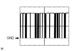
(a) Waveform 1:
|
Item |
Content |
|---|---|
|
Terminal No. |
F72-3 (LIN1) - F72-29 (GND) |
|
Tool Setting |
2 V/DIV., 20 ms./DIV. |
|
Vehicle Condition |
Ignition switch ON |
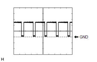
(b) Waveform 2:
|
Item |
Content |
|---|---|
|
Terminal No. |
F72-15 (SOL-) - F72-29 (GND) |
|
Tool Setting |
5 V/DIV., 1 ms./DIV. |
|
Vehicle Condition |
|
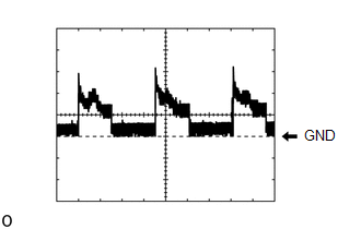
(c) Waveform 3:

|
Item |
Content |
|---|---|
|
Terminal No. |
F7A-2 (B2AI) - Body ground |
|
F7A-3 (A2AI) - Body ground |
|
|
F7A-9 (A1AI) - Body ground |
|
|
F7A-10 (B1AI) - Body ground |
|
|
Tool Setting |
2 V/DIV., 10 ms./DIV. |
|
Vehicle Condition |
|
(d) Waveform 4:

|
Item |
Content |
|---|---|
|
Terminal No. |
F7A-4 (A2AO) - Body ground |
|
F7A-6 (B2AO) - Body ground |
|
|
F7A-8 (B1AO) - Body ground |
|
|
F7A-16 (A1AO) - Body ground |
|
|
Tool Setting |
2 V/DIV., 10 ms./DIV. |
|
Vehicle Condition |
|
(e) Waveform 5:
|
Item |
Content |
|---|---|
|
Terminal No. |
F7A-18 (B2LL) - Body ground |
|
F7A-20 (A1LL) - Body ground |
|
|
F7A-35 (B1LL) - Body ground |
|
|
F7A-37 (A2LL) - Body ground |
|
|
Tool Setting |
2 V/DIV., 10 ms./DIV. |
|
Vehicle Condition |
|
(f) Waveform 6:

|
Item |
Content |
|---|---|
|
Terminal No. |
F7A-19 (B1LU) - Body ground |
|
F7A-30 (A2LU) - Body ground |
|
|
F7A-31 (B2LU) - Body ground |
|
|
F7A-36 (A1LU) - Body ground |
|
|
Tool Setting |
2 V/DIV., 10 ms./DIV. |
|
Vehicle Condition |
|
(g) Waveform 7:

|
Item |
Content |
|---|---|
|
Terminal No. |
F7A-23 (A2RL) - Body ground |
|
F7A-25 (B2RL) - Body ground |
|
|
F7A-26 (B1RL) - Body ground |
|
|
F7A-28 (A1RL) - Body ground |
|
|
Tool Setting |
2 V/DIV., 10 ms./DIV. |
|
Vehicle Condition |
|
(h) Waveform 8:

|
Item |
Content |
|---|---|
|
Terminal No. |
F7A-22 (B1RU) - Body ground |
|
F7A-24 (A1RU) - Body ground |
|
|
F7A-27 (A2RU) - Body ground |
|
|
F7A-29 (B2RU) - Body ground |
|
|
Tool Setting |
2 V/DIV., 10 ms./DIV. |
|
Vehicle Condition |
|
(i) Waveform 9:
|
Item |
Content |
|---|---|
|
Terminal No. |
F7A-40 (BLW) - F72-29 (GND) |
|
Tool Setting |
2 V/DIV., 1 ms./DIV. |
|
Vehicle Condition |
|
AIR CONDITIONING CONTROL ASSEMBLY
HINT:
Check from the rear of the connector while it is connected to the air conditioning control assembly.
|
Terminal No. (symbol) |
Wiring Color |
Terminal Description |
Condition |
Specified Condition |
|---|---|---|---|---|
|
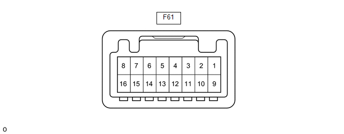
F61-2 (LIN1) - Body ground |
L - Body ground |
LIN communication |
Ignition switch ON |
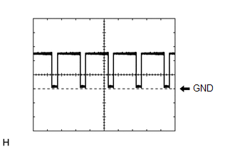
Pulse generation (See waveform 1) |
|
F61-10 (IG+) - Body ground |
BE - Body ground |
Power source (IG) |
Ignition switch off |
Below 1 V |
|
Ignition switch ON |
11 to 14 V |
|||
|
F61-16 (GND) - Body ground |
W-B - Body ground |
Ground for air conditioning control assembly |
Always |
Below 1 V |
(a) Waveform 1:
|
Item |
Content |
|---|---|
|
Terminal No. |
F61-2 (LIN1) - Body ground |
|
Tool Setting |
2 V/DIV., 20 ms./DIV. |
|
Vehicle Condition |
Ignition switch ON |

 Problem Symptoms Table
PROBLEM SYMPTOMS TABLE
HINT:
Use the table below to help determine the cause of problem symptoms.
If multiple suspected areas are listed, the potential causes of the symptoms
are lis ...
 Diagnosis System
DIAGNOSIS SYSTEM
DESCRIPTION
Air conditioning system data and Diagnostic Trouble Codes (DTCs) can be read
through the Data Link Connector 3 (DLC3) of the vehicle. When the system seems to
be mal ...
Other materials:
Toyota CH-R Service Manual > Clock System: Parts Location
PARTS LOCATION
ILLUSTRATION
*1
CLOCK ASSEMBLY
*2
MAIN BODY ECU (MULTIPLEX NETWORK BODY ECU)
*3
INSTRUMENT PANEL JUNCTION BLOCK ASSEMBLY
- ECU-DCC NO. 2 FUSE
- ECU-ACC FUSE
- PANEL FUSE
- ECU-IG1 NO. 4 FUSE
- A ...
Toyota CH-R Service Manual > Brake Booster: Components
COMPONENTS
ILLUSTRATION
*1
NO. 1 ENGINE UNDER COVER
-
-
N*m (kgf*cm, ft.*lbf): Specified torque
-
-
ILLUSTRATION
*1
DASH PANEL HEAT INSULATOR
-
-
...
Toyota C-HR (AX20) 2023-2026 Owner's Manual
Toyota CH-R Owners Manual
- For safety and security
- Instrument cluster
- Operation of each component
- Driving
- Interior features
- Maintenance and care
- When trouble arises
- Vehicle specifications
- For owners
Toyota CH-R Service Manual
- Introduction
- Maintenance
- Audio / Video
- Cellular Communication
- Navigation / Multi Info Display
- Park Assist / Monitoring
- Brake (front)
- Brake (rear)
- Brake Control / Dynamic Control Systems
- Brake System (other)
- Parking Brake
- Axle And Differential
- Drive Shaft / Propeller Shaft
- K114 Cvt
- 3zr-fae Battery / Charging
- Networking
- Power Distribution
- Power Assist Systems
- Steering Column
- Steering Gear / Linkage
- Alignment / Handling Diagnosis
- Front Suspension
- Rear Suspension
- Tire / Wheel
- Tire Pressure Monitoring
- Door / Hatch
- Exterior Panels / Trim
- Horn
- Lighting (ext)
- Mirror (ext)
- Window / Glass
- Wiper / Washer
- Door Lock
- Heating / Air Conditioning
- Interior Panels / Trim
- Lighting (int)
- Meter / Gauge / Display
- Mirror (int)
- Power Outlets (int)
- Pre-collision
- Seat
- Seat Belt
- Supplemental Restraint Systems
- Theft Deterrent / Keyless Entry

0.0072