Toyota CH-R Service Manual: Brake Warning Light Remains ON
DESCRIPTION
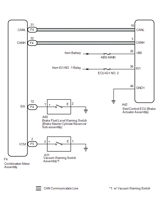
The skid control ECU (brake actuator assembly) is connected to the combination meter assembly via CAN communication.
If any of the following is detected, the brake system warning light (red indicator) remains on:
- The skid control ECU (brake actuator assembly) connector is disconnected from the skid control ECU (brake actuator assembly).
- The brake fluid level is insufficient.
- The vacuum inside the brake booster decreases. (w/ Vacuum Warning Switch)
- EBD operation is not possible.
WIRING DIAGRAM
CAUTION / NOTICE / HINT
NOTICE:
- When replacing the skid control ECU (brake actuator assembly), perform
system variant learning.
Click here
.gif)
- Inspect the fuses for circuits related to this system before performing the following procedure.
PROCEDURE
|
1. |
CHECK CAN COMMUNICATION SYSTEM |
(a) Check if CAN communication system DTCs are output.
Click here
|
Result |
Proceed to |
|---|---|
|
DTCs are not output. |
A |
|
DTCs are output. |
B |
| B | .gif) |
INSPECT CAN COMMUNICATION SYSTEM
|
|
.gif)
|
2. |
CHECK IF BRAKE ACTUATOR ASSEMBLY CONNECTOR IS SECURELY CONNECTED |
(a) Check if the skid control ECU (brake actuator assembly) connector is securely connected.
OK:
The connector is securely connected.
| NG | |
CONNECT CONNECTOR TO ECU CORRECTLY |
|
|
3. |
CHECK BATTERY |
(a) Check the battery voltage.
Standard Voltage:
11 to 14 V
| NG | |
CHECK OR REPLACE CHARGING SYSTEM COMPONENT OR BATTERY |
|
|
4. |
CHECK HARNESS AND CONNECTOR (POWER SOURCE (+BS) TERMINAL) |
|
(a) Disconnect the A42 skid control ECU (brake actuator assembly) connector. |
|
.png)
(b) Measure the voltage according to the value(s) in the table below.
Standard Voltage:
|
Tester Connection |
Condition |
Specified Condition |
|---|---|---|
|
A42-30 (+BS) - Body ground |
Always |
11 to 14 V |
| NG | |
REPAIR OR REPLACE HARNESS OR CONNECTOR (POWER SOURCE CIRCUIT) |
|
|
5. |
CHECK HARNESS AND CONNECTOR (POWER SOURCE (IG1) TERMINAL) |
|
(a) Disconnect the A42 skid control ECU (brake actuator assembly) connector. |
|
.png)
(b) Measure the voltage according to the value(s) in the table below.
Standard Voltage:
|
Tester Connection |
Condition |
Specified Condition |
|---|---|---|
|
A42-36 (IG1) - Body ground |
Ignition switch ON |
11 to 14 V |
| NG | |
REPAIR OR REPLACE HARNESS OR CONNECTOR (POWER SOURCE CIRCUIT) |
|
|
6. |
CHECK HARNESS AND CONNECTOR (GND1 TERMINAL) |
|
(a) Turn the ignition switch off. |
|
.png)
(b) Measure the resistance according to the value(s) in the table below.
Standard Resistance:
|
Tester Connection |
Condition |
Specified Condition |
|---|---|---|
|
A42-46 (GND1) - Body ground |
Always |
Below 1 Ω |
| NG | |
REPAIR OR REPLACE HARNESS OR CONNECTOR (GND1 CIRCUIT) |
|
|
7. |
INSPECT BRAKE FLUID LEVEL WARNING SWITCH |
|
(a) Turn the ignition switch off. |
|
(b) Remove the reservoir filler cap and strainer.
(c) Disconnect the A60 brake fluid level warning switch connector.
(d) Measure the resistance according to the value(s) in the table below.
HINT:
A float is located inside the reservoir. Its position changes according to the brake fluid level.
Standard Resistance:
|
Tester Connection |
Condition |
Specified Condition |
|---|---|---|
|
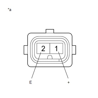
1 (+) - 2 (E) |
Switch OFF (Float up) |
1.9 to 2.1 kΩ |
|
1 (+) - 2 (E) |
Switch ON (Float down) |
Below 1 Ω |
HINT:
If there is no problem after finishing the above check, adjust the brake fluid level to the MAX level.
| NG | |
REPLACE BRAKE MASTER CYLINDER RESERVOIR SUB-ASSEMBLY |
|
|
8. |
CHECK HARNESS AND CONNECTOR (COMBINATION METER ASSEMBLY - BRAKE FLUID LEVEL WARNING SWITCH) |
(a) Disconnect the F4 combination meter assembly connector.
(b) Measure the resistance according to the value(s) in the table below.
Standard Resistance:
|
Tester Connection |
Condition |
Specified Condition |
|---|---|---|
|
F4-12 (SW) - A60-1 (+) |
Always |
Below 1 Ω |
|
F4-12 (SW) or A60-1 (+) - Body ground |
Always |
10 kΩ or higher |
|
A60-2 (E) - Body ground |
Always |
Below 1 Ω |
| NG | |
REPAIR OR REPLACE HARNESS OR CONNECTOR |
|
|
9. |
INSPECT VACUUM WARNING SWITCH ASSEMBLY |
(a) Inspect the vacuum warning switch assembly.
Click here
OK:
The vacuum warning switch assembly is normal.
| NG | |
REPLACE VACUUM WARNING SWITCH ASSEMBLY |
|
|
10. |
CHECK HARNESS AND CONNECTOR (BRAKE WARNING LIGHT CIRCUIT) |
(a) Disconnect the F5 combination meter connector.
(b) Measure the resistance according to the value(s) in the table below.
Standard Resistance:
|
Tester Connection |
Condition |
Specified Condition |
|---|---|---|
|
F5-2 (VCM) - A31-2 (+) |
Always |
Below 1 Ω |
|
F5-2 (VCM) or A31-2 (+) - Body ground |
Always |
10 kΩ or higher |
|
A31-1 (E) - Body ground |
Always |
Below 1 Ω |
| NG | |
REPAIR OR REPLACE HARNESS OR CONNECTOR |
|
|
11. |
READ VALUE USING TECHSTREAM (BRAKE WARNING LIGHT) |
(a) Reconnect the A41 skid control ECU (brake actuator assembly) connector.
(b) Select the Data List on the Techstream.
Click here
|
Tester Display |
Measurement Item |
Range |
Normal Condition |
Diagnostic Note |
|---|---|---|---|---|
|
Brake Warning Light |
Brake system warning light (red indicator) |
ON or OFF |
ON: Warning light on OFF: Warning light off |
- |
|
Tester Display |
|---|
|
Brake Warning Light |
(c) Check the Techstream display condition of the brake system warning light (red indicator).
|
Result |
Proceed to |
|---|---|
|
ON is displayed. |
A |
|
OFF is displayed. |
B |
| A | |
REPLACE BRAKE ACTUATOR ASSEMBLY |
| B | |
INSPECT METER / GAUGE SYSTEM |
 ABS Warning Light does not Come ON
DESCRIPTION
The skid control ECU (brake actuator assembly) is connected to the combination
meter assembly via CAN communication.
CAUTION / NOTICE / HINT
NOTICE:
When replacing the skid control E ...
 Brake Warning Light does not Come ON
DESCRIPTION
The skid control ECU (brake actuator assembly) is connected to the combination
meter assembly via CAN communication.
CAUTION / NOTICE / HINT
NOTICE:
When replacing the skid c ...
Other materials:
Toyota CH-R Service Manual > Audio And Visual System(for Radio And Display Type): Parts Location
PARTS LOCATION
ILLUSTRATION
*1
MAP LIGHT ASSEMBLY (TELEPHONE MICROPHONE ASSEMBLY)
*2
SKID CONTROL ECU (BRAKE ACTUATOR ASSEMBLY)
ILLUSTRATION
*1
FRONT NO. 1 SPEAKER ASSEMBLY LH
*2
FRONT NO. 1 SPEA ...
Toyota CH-R Service Manual > Power Mirror Control System: How To Proceed With Troubleshooting
CAUTION / NOTICE / HINT
HINT:
Use the following procedure to troubleshoot the power mirror control
system.
*: Use the Techstream.
PROCEDURE
1.
VEHICLE BROUGHT TO WORKSHOP
NEXT
...
Toyota C-HR (AX20) 2023-2026 Owner's Manual
Toyota CH-R Owners Manual
- For safety and security
- Instrument cluster
- Operation of each component
- Driving
- Interior features
- Maintenance and care
- When trouble arises
- Vehicle specifications
- For owners
Toyota CH-R Service Manual
- Introduction
- Maintenance
- Audio / Video
- Cellular Communication
- Navigation / Multi Info Display
- Park Assist / Monitoring
- Brake (front)
- Brake (rear)
- Brake Control / Dynamic Control Systems
- Brake System (other)
- Parking Brake
- Axle And Differential
- Drive Shaft / Propeller Shaft
- K114 Cvt
- 3zr-fae Battery / Charging
- Networking
- Power Distribution
- Power Assist Systems
- Steering Column
- Steering Gear / Linkage
- Alignment / Handling Diagnosis
- Front Suspension
- Rear Suspension
- Tire / Wheel
- Tire Pressure Monitoring
- Door / Hatch
- Exterior Panels / Trim
- Horn
- Lighting (ext)
- Mirror (ext)
- Window / Glass
- Wiper / Washer
- Door Lock
- Heating / Air Conditioning
- Interior Panels / Trim
- Lighting (int)
- Meter / Gauge / Display
- Mirror (int)
- Power Outlets (int)
- Pre-collision
- Seat
- Seat Belt
- Supplemental Restraint Systems
- Theft Deterrent / Keyless Entry

0.0091