Toyota CH-R Service Manual: Steering Angle Sensor Output Malfunction (C1434)
DESCRIPTION
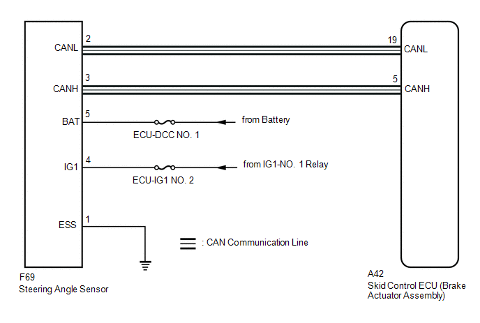
The skid control ECU (brake actuator assembly) receives signals from the steering angle sensor via CAN communication.
HINT:
If there is a malfunction in the bus lines between the steering angle sensor and the CAN communication system, DTC U0126 (Lost Communication with Steering Angle Sensor Module) is output. When U0126 is output together with C1434, inspect and repair the trouble areas indicated by U0126 first.
DTCs may be stored if one of the following occurs:
- Steering angle sensor zero point value malfunction.
- Steering angle sensor signal malfunction.
- Steering angle sensor signal stuck malfunction.
- Steering angle sensor and the yaw rate sensor values inconsistent.
- Steering angle sensor installation abnormality.
|
DTC No. |
Detection Item |
DTC Detection Condition |
Trouble Area |
|---|---|---|---|
|
C1434 |
Steering Angle Sensor Output Malfunction |
Any of the following is detected:
|
|
|
Vehicle Condition |
||||
|---|---|---|---|---|
|
Pattern 1 |
Pattern 2 |
Pattern 3 |
||
|
Diagnosis Condition |
- |
- |
- |
- |
|
Malfunction Status |
The difference between zero point stored in the steering angle sensor and the estimated zero point exceeds 15 deg. |
○ |
- |
- |
|
The offset value of the steering angle sensor is -13.5 deg. or less or 13.5 deg. or more. |
- |
○ |
- |
|
|
The steering angle sensor value exceeds a specified value. |
- |
- |
○ |
|
|
Detection Time |
- |
- |
0.3 seconds or more |
|
|
Number of Trips |
1 trip |
1 trip |
1 trip |
|
HINT:
DTC will be output when conditions for either of the patterns in the table above are met.
DTC Detection Conditions: C1434|
Vehicle Condition |
||||
|---|---|---|---|---|
|
Pattern 4 |
Pattern 5 |
Pattern 6 |
||
|
Diagnosis Condition |
- |
- |
- |
- |
|
Malfunction Status |
The change of the steering angle sensor value within 0.02 seconds is abnormal. |
○ |
- |
- |
|
The steering angle sensor value changes by less than 5 deg. and both left and right turns have been recognized. |
- |
○ |
- |
|
|
There is a difference between the skid control ECU (brake actuator assembly) estimated value and the steering angle sensor value due to an abnormal steering angle sensor value. |
- |
- |
○ |
|
|
Detection Time |
- |
- |
- |
|
|
Number of Trips |
1 trip |
1 trip |
1 trip |
|
HINT:
DTC will be output when conditions for either of the patterns in the table above are met.
WIRING DIAGRAM
CAUTION / NOTICE / HINT
NOTICE:
Inspect the fuses for circuits related to this system before performing the following procedure.
HINT:
- When U0073, U0123 and/or U0126 is output together with C1434, inspect
and repair the trouble areas indicated by U0073, U0123 and/or U0126 first.
Click here
.gif)
- When a speed sensor or the yaw rate and acceleration sensor (airbag sensor assembly) is malfunctioning, DTCs for the steering angle sensor may be stored even though the steering angle sensor is normal. When DTCs for a speed sensor or yaw rate and acceleration sensor (airbag sensor assembly) are output together with DTCs for the steering angle sensor, inspect and repair the speed sensor or yaw rate and acceleration sensor (airbag sensor assembly) first, and then inspect and repair the steering angle sensor.
PROCEDURE
|
1. |
CHECK DTC |
(a) Clear the DTCs.
Click here
(b) Turn the ignition switch off.
(c) Turn the ignition switch to ON again and check that no CAN communication system DTCs are output.
Click here
(d) Start the engine.
(e) Drive the vehicle at a speed of 50 km/h (31 mph) and turn the steering wheel to the right and left and then check that no speed sensor or yaw rate and acceleration sensor (airbag sensor assembly) DTCs are output.
Click here
|
Result |
Proceed to |
|---|---|
|
No CAN communication system, speed sensor, or yaw rate and acceleration sensor (airbag sensor assembly) DTCs are output. |
A |
|
CAN communication system DTCs are output. |
B |
|
Speed sensor and/or yaw rate and acceleration sensor (airbag sensor assembly) DTCs are output. |
C |
HINT:
- If a speed sensor or the yaw rate and acceleration sensor (airbag sensor assembly) is malfunctioning, DTCs for the steering angle sensor may be stored even though the steering angle sensor is normal.
- If speed sensor and yaw rate and acceleration sensor (airbag sensor assembly) DTCs are output simultaneously, repair these malfunctions and then inspect the steering angle sensor.
| B | .gif) |
INSPECT CAN COMMUNICATION SYSTEM
|
| C | |
REPAIR CIRCUIT INDICATED BY OUTPUT DTC
|
|
.gif)
|
2. |
CHECK STEERING ANGLE SENSOR INSTALLATION |
(a) Turn the ignition switch off.
(b) Check that the steering angle sensor has been installed properly.
Click here
OK:
The steering angle sensor installation is normal.
| NG | |
INSTALL STEERING ANGLE SENSOR CORRECTLY |
|
|
3. |
CHECK HARNESS AND CONNECTOR (POWER SOURCE TERMINAL) |
|
(a) Remove the steering wheel and column cover. |
|
.png)
(b) Make sure that there is no looseness at the locking part and the connecting part of the connector.
(c) Disconnect the F69 steering angle sensor connector.
(d) Measure the voltage according to the value(s) in the table below.
Standard Voltage:
|
Tester Connection |
Condition |
Specified Condition |
|---|---|---|
|
F69-5 (BAT) - Body ground |
Always |
11 to 14 V |
|
F69-4 (IG1) - Body ground |
Ignition switch ON |
11 to 14 V |
|
Result |
Proceed to |
|---|---|
|
OK |
A |
|
NG |
B |
| B | |
REPAIR OR REPLACE HARNESS OR CONNECTOR (POWER SOURCE CIRCUIT) |
|
|
4. |
CHECK HARNESS AND CONNECTOR (GROUND TERMINAL) |
|
(a) Turn the ignition switch off. |
|
.png)
(b) Measure the resistance according to the value(s) in the table below.
Standard Resistance:
|
Tester Connection |
Condition |
Specified Condition |
|---|---|---|
|
E69-1 (ESS) - Body ground |
Always |
Below 1 Ω |
HINT:
If troubleshooting has been carried out according to Problem Symptoms Table, refer back to the table and proceed to the next step before replacing parts.
Click here
| OK | |
REPLACE STEERING ANGLE SENSOR |
| NG | |
REPAIR OR REPLACE HARNESS OR CONNECTOR (GROUND CIRCUIT) |
 Steering Angle Sensor Internal Circuit (C1433)
DESCRIPTION
This DTC is stored when the skid control ECU (brake actuator assembly) receives
an internal malfunction signal from the steering angle sensor.
DTC No.
Detection I ...
 Yaw Rate Sensor Malfunction (C1436)
DESCRIPTION
This DTC is stored when the skid control ECU (brake actuator assembly) detects
improper installation of the yaw rate and acceleration sensor (airbag sensor assembly)
or an abnormality ...
Other materials:
Toyota CH-R Service Manual > Smart Key System(for Start Function): Diagnostic Trouble Code Chart
DIAGNOSTIC TROUBLE CODE CHART
Smart Key System (for Start Function)
DTC No.
Detection Item
Link
B2271
Ignition Hold Monitor Malfunction
B2274
ACC Monitor Malfunction
...
Toyota CH-R Service Manual > Power Window Regulator Motor(for Rear Door): Inspection
INSPECTION
CAUTION / NOTICE / HINT
NOTICE:
Do not apply positive (+) battery voltage to any terminals, except terminal
2 (B), to avoid damaging the pulse sensor inside the motor.
Perform initialization of the power window system after removing, inspecting
or replacing the powe ...
Toyota C-HR (AX20) 2023-2026 Owner's Manual
Toyota CH-R Owners Manual
- For safety and security
- Instrument cluster
- Operation of each component
- Driving
- Interior features
- Maintenance and care
- When trouble arises
- Vehicle specifications
- For owners
Toyota CH-R Service Manual
- Introduction
- Maintenance
- Audio / Video
- Cellular Communication
- Navigation / Multi Info Display
- Park Assist / Monitoring
- Brake (front)
- Brake (rear)
- Brake Control / Dynamic Control Systems
- Brake System (other)
- Parking Brake
- Axle And Differential
- Drive Shaft / Propeller Shaft
- K114 Cvt
- 3zr-fae Battery / Charging
- Networking
- Power Distribution
- Power Assist Systems
- Steering Column
- Steering Gear / Linkage
- Alignment / Handling Diagnosis
- Front Suspension
- Rear Suspension
- Tire / Wheel
- Tire Pressure Monitoring
- Door / Hatch
- Exterior Panels / Trim
- Horn
- Lighting (ext)
- Mirror (ext)
- Window / Glass
- Wiper / Washer
- Door Lock
- Heating / Air Conditioning
- Interior Panels / Trim
- Lighting (int)
- Meter / Gauge / Display
- Mirror (int)
- Power Outlets (int)
- Pre-collision
- Seat
- Seat Belt
- Supplemental Restraint Systems
- Theft Deterrent / Keyless Entry

0.0095