Toyota CH-R Service Manual: Open in Front Speed Sensor RH (C1330-C1467)
DESCRIPTION
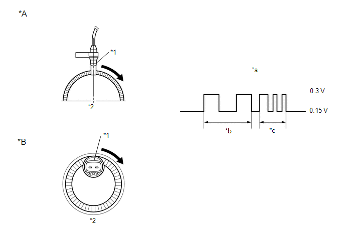
Each speed sensor detects wheel speed and sends signals to the skid control ECU (brake actuator assembly). These signals are used by the ABS.
HINT:
The output voltage values shown below are for when the vehicle wire harnesses are connected to the skid control ECU (brake actuator assembly) and the speed sensors.
|
*A |
for Front |
*B |
for Rear |
|
*1 |
Speed Sensor |
*2 |
Speed Sensor Rotor |
|
*a |
Waveform (Reference): Between Speed Sensor (-) and Body Ground |
*b |
Low speed |
|
*c |
High speed |
- |
- |
|
DTC No. |
Detection Item |
DTC Detection Condition |
Trouble Area |
|---|---|---|---|
|
C1330 |
Open in Front Speed Sensor RH |
An open or short in the speed sensor signal circuit. |
|
|
C1331 |
Open in Front Speed Sensor LH |
An open or short in the speed sensor signal circuit. |
|
|
C1332 |
Open in Rear Speed Sensor RH |
An open or short in the speed sensor signal circuit. |
|
|
C1333 |
Open in Rear Speed Sensor LH |
An open or short in the speed sensor signal circuit. |
|
|
C1464 |
Front Speed Sensor RH |
Any of the following is detected:
|
|
|
C1465 |
Front Speed Sensor LH |
Any of the following is detected:
|
|
|
C1466 |
Rear Speed Sensor RH |
Any of the following is detected:
|
|
|
C1467 |
Rear Speed Sensor LH |
Any of the following is detected:
|
|
|
Vehicle Condition |
|||||
|---|---|---|---|---|---|
|
Pattern 1 |
Pattern 2 |
Pattern 3 |
Pattern 4 |
||
|
Diagnosis Condition |
- |
- |
- |
- |
- |
|
Malfunction Status |
The vehicle speed is more than 50.4 km/h (31 mph) and pulses are not input. |
○ |
- |
- |
- |
|
After the initial start or restart and when the vehicle speed has reached 12 km/h (7 mph), a wheel speed of 0 km/h (0 mph) is detected. |
- |
○ |
- |
- |
|
|
After the initial start or restart and when the vehicle speed has reached 20 km/h (12 mph), a rear wheel speed of 0 km/h (0 mph) is detected. |
- |
- |
○ |
- |
|
|
The difference between the speed of the fastest wheel and the speed of the slowest wheel is 5% or more of vehicle speed. (If the speed of any wheel is less than 5 km/h (3 mph), a speed difference of up to 15% is allowable.) |
- |
- |
- |
○ |
|
|
Detection Time |
0.08 seconds |
- |
- |
9 to 72 seconds or more (varies depending on the driving conditions) |
|
|
Number of Trips |
1 trip |
1 trip |
1 trip |
1 trip |
|
HINT:
DTC will be output when conditions for either of the patterns in the table above are met.
DTC Detection Conditions: C1464|
Vehicle Condition |
|||||
|---|---|---|---|---|---|
|
Pattern 5 |
Pattern 6 |
Pattern 7 |
Pattern 8 |
||
|
Diagnosis Condition |
- |
- |
- |
- |
- |
|
Malfunction Status |
The vehicle speed is less than 100 km/h (62 mph) and the difference between the speed of the fastest wheel and the speed of the slowest wheel is 6 km/h (4 mph) or more. (If the speed of any wheel is less than 5 km/h (3 mph), a speed difference of up to 16 km/h (10 mph) is allowable.) |
○ |
- |
- |
- |
|
The vehicle speed is 100 km/h (62 mph) or more and the difference between the speed of the fastest wheel and the speed of the slowest wheel is 6% or more of vehicle speed. (If the speed of any wheel is less than 5 km/h (3 mph), a speed difference of up to 15% is allowable.) |
- |
○ |
- |
- |
|
|
Wheel speed sensor signal fluctuation is equivalent to 98 G or more, or alternates between 50 G or more and -50 G or less. |
- |
- |
○ |
- |
|
|
An abnormal signal is received from a wheel speed sensor. |
- |
- |
- |
○ |
|
|
Detection Time |
9 to 72 seconds or more (varies depending on the driving conditions) |
9 to 72 seconds or more (varies depending on the driving conditions) |
- |
- |
|
|
Number of Trips |
1 trip |
1 trip |
1 trip |
1 trip |
|
HINT:
DTC will be output when conditions for either of the patterns in the table above are met.
DTC Detection Conditions: C1465|
Vehicle Condition |
|||||
|---|---|---|---|---|---|
|
Pattern 1 |
Pattern 2 |
Pattern 3 |
Pattern 4 |
||
|
Diagnosis Condition |
- |
- |
- |
- |
- |
|
Malfunction Status |
The vehicle speed is more than 50.4 km/h (31 mph) and pulses are not input. |
○ |
- |
- |
- |
|
After the initial start or restart and when the vehicle speed has reached 12 km/h (7 mph), a wheel speed of 0 km/h (0 mph) is detected. |
- |
○ |
- |
- |
|
|
After the initial start or restart and when the vehicle speed has reached 20 km/h (12 mph), a rear wheel speed of 0 km/h (0 mph) is detected. |
- |
- |
○ |
- |
|
|
The difference between the speed of the fastest wheel and the speed of the slowest wheel is 5% or more of vehicle speed. (If the speed of any wheel is less than 5 km/h (3 mph), a speed difference of up to 15% is allowable.) |
- |
- |
- |
○ |
|
|
Detection Time |
0.08 seconds |
- |
- |
9 to 72 seconds or more (varies depending on the driving conditions) |
|
|
Number of Trips |
1 trip |
1 trip |
1 trip |
1 trip |
|
HINT:
DTC will be output when conditions for either of the patterns in the table above are met.
DTC Detection Conditions: C1465|
Vehicle Condition |
|||||
|---|---|---|---|---|---|
|
Pattern 5 |
Pattern 6 |
Pattern 7 |
Pattern 8 |
||
|
Diagnosis Condition |
- |
- |
- |
- |
- |
|
Malfunction Status |
The vehicle speed is less than 100 km/h (62 mph) and the difference between the speed of the fastest wheel and the speed of the slowest wheel is 6 km/h (4 mph) or more. (If the speed of any wheel is less than 5 km/h (3 mph), a speed difference of up to 16 km/h (10 mph) is allowable.) |
○ |
- |
- |
- |
|
The vehicle speed is 100 km/h (62 mph) or more and the difference between the speed of the fastest wheel and the speed of the slowest wheel is 6% or more of vehicle speed. (If the speed of any wheel is less than 5 km/h (3 mph), a speed difference of up to 15% is allowable.) |
- |
○ |
- |
- |
|
|
Wheel speed sensor signal fluctuation is equivalent to 98 G or more, or alternates between 50 G or more and -50 G or less. |
- |
- |
○ |
- |
|
|
An abnormal signal is received from a wheel speed sensor. |
- |
- |
- |
○ |
|
|
Detection Time |
9 to 72 seconds or more (varies depending on the driving conditions) |
9 to 72 seconds or more (varies depending on the driving conditions) |
- |
- |
|
|
Number of Trips |
1 trip |
1 trip |
1 trip |
1 trip |
|
HINT:
DTC will be output when conditions for either of the patterns in the table above are met.
DTC Detection Conditions: C1466|
Vehicle Condition |
|||||
|---|---|---|---|---|---|
|
Pattern 1 |
Pattern 2 |
Pattern 3 |
Pattern 4 |
||
|
Diagnosis Condition |
- |
- |
- |
- |
- |
|
Malfunction Status |
The vehicle speed is more than 43.2 km/h (27 mph) and pulses are not input. |
○ |
- |
- |
- |
|
After the initial start or restart and when the vehicle speed has reached 12 km/h (7 mph), a wheel speed of 0 km/h (0 mph) is detected. |
- |
○ |
- |
- |
|
|
After the initial start or restart and when the vehicle speed has reached 20 km/h (12 mph), a rear wheel speed of 0 km/h (0 mph) is detected. |
- |
- |
○ |
- |
|
|
The difference between the speed of the fastest wheel and the speed of the slowest wheel is 5% or more of vehicle speed. (If the speed of any wheel is less than 5 km/h (3 mph), a speed difference of up to 15% is allowable.) |
- |
- |
- |
○ |
|
|
Detection Time |
0.08 seconds |
- |
- |
9 to 72 seconds or more (varies depending on the driving conditions) |
|
|
Number of Trips |
1 trip |
1 trip |
1 trip |
1 trip |
|
HINT:
DTC will be output when conditions for either of the patterns in the table above are met.
DTC Detection Conditions: C1466|
Vehicle Condition |
|||||
|---|---|---|---|---|---|
|
Pattern 5 |
Pattern 6 |
Pattern 7 |
Pattern 8 |
||
|
Diagnosis Condition |
- |
- |
- |
- |
- |
|
Malfunction Status |
The vehicle speed is less than 100 km/h (62 mph) and the difference between the speed of the fastest wheel and the speed of the slowest wheel is 6 km/h (4 mph) or more. (If the speed of any wheel is less than 5 km/h (3 mph), a speed difference of up to 16 km/h (10 mph) is allowable.) |
○ |
- |
- |
- |
|
The vehicle speed is 100 km/h (62 mph) or more and the difference between the speed of the fastest wheel and the speed of the slowest wheel is 6% or more of vehicle speed. (If the speed of any wheel is less than 5 km/h (3 mph), a speed difference of up to 15% is allowable.) |
- |
○ |
- |
- |
|
|
Wheel speed sensor signal fluctuation is equivalent to 98 G or more, or alternates between 50 G or more and -50 G or less. |
- |
- |
○ |
- |
|
|
An abnormal signal is received from a wheel speed sensor. |
- |
- |
- |
○ |
|
|
Detection Time |
9 to 72 seconds or more (varies depending on the driving conditions) |
9 to 72 seconds or more (varies depending on the driving conditions) |
- |
- |
|
|
Number of Trips |
1 trip |
1 trip |
1 trip |
1 trip |
|
HINT:
DTC will be output when conditions for either of the patterns in the table above are met.
DTC Detection Conditions: C1467|
Vehicle Condition |
|||||
|---|---|---|---|---|---|
|
Pattern 1 |
Pattern 2 |
Pattern 3 |
Pattern 4 |
||
|
Diagnosis Condition |
- |
- |
- |
- |
- |
|
Malfunction Status |
The vehicle speed is more than 43.2 km/h (27 mph) and pulses are not input. |
○ |
- |
- |
- |
|
After the initial start or restart and when the vehicle speed has reached 12 km/h (7 mph), a wheel speed of 0 km/h (0 mph) is detected. |
- |
○ |
- |
- |
|
|
After the initial start or restart and when the vehicle speed has reached 20 km/h (12 mph), a rear wheel speed of 0 km/h (0 mph) is detected. |
- |
- |
○ |
- |
|
|
The difference between the speed of the fastest wheel and the speed of the slowest wheel is 5% or more of vehicle speed. (If the speed of any wheel is less than 5 km/h (3 mph), a speed difference of up to 15% is allowable.) |
- |
- |
- |
○ |
|
|
Detection Time |
0.08 seconds |
- |
- |
9 to 72 seconds or more (varies depending on the driving conditions) |
|
|
Number of Trips |
1 trip |
1 trip |
1 trip |
1 trip |
|
HINT:
DTC will be output when conditions for either of the patterns in the table above are met.
DTC Detection Conditions: C1467|
Vehicle Condition |
|||||
|---|---|---|---|---|---|
|
Pattern 5 |
Pattern 6 |
Pattern 7 |
Pattern 8 |
||
|
Diagnosis Condition |
- |
- |
- |
- |
- |
|
Malfunction Status |
The vehicle speed is less than 100 km/h (62 mph) and the difference between the speed of the fastest wheel and the speed of the slowest wheel is 6 km/h (4 mph) or more. (If the speed of any wheel is less than 5 km/h (3 mph), a speed difference of up to 16 km/h (10 mph) is allowable.) |
○ |
- |
- |
- |
|
The vehicle speed is 100 km/h (62 mph) or more and the difference between the speed of the fastest wheel and the speed of the slowest wheel is 6% or more of vehicle speed. (If the speed of any wheel is less than 5 km/h (3 mph), a speed difference of up to 15% is allowable.) |
- |
○ |
- |
- |
|
|
Wheel speed sensor signal fluctuation is equivalent to 98 G or more, or alternates between 50 G or more and -50 G or less. |
- |
- |
○ |
- |
|
|
An abnormal signal is received from a wheel speed sensor. |
- |
- |
- |
○ |
|
|
Detection Time |
9 to 72 seconds or more (varies depending on the driving conditions) |
9 to 72 seconds or more (varies depending on the driving conditions) |
- |
- |
|
|
Number of Trips |
1 trip |
1 trip |
1 trip |
1 trip |
|
HINT:
DTC will be output when conditions for either of the patterns in the table above are met.
WIRING DIAGRAM
CAUTION / NOTICE / HINT
NOTICE:
When replacing the skid control ECU (brake actuator assembly), perform system variant learning.
Click here
.gif)
PROCEDURE
|
1. |
RECONFIRM DTC |
(a) Check if the same DTC is output.
Click here
|
Result |
Proceed to |
|---|---|
|
DTCs C1330 and/or C1464 are output. |
A |
|
DTCs C1331 and/or C1465 are output. |
B |
|
DTCs C1332 and/or C1466 are output. |
C |
|
DTCs C1333 and/or C1467 are output. |
D |
| B | .gif) |
GO TO STEP 9 |
| C | |
GO TO STEP 16 |
| D | |
GO TO STEP 23 |
|
.gif)
|
2. |
CHECK FRONT SPEED SENSOR RH INSTALLATION |
|
(a) Turn the ignition switch off. |
|
.png)
(b) Check the speed sensor installation.
OK:
There is no clearance between the sensor and the front steering knuckle RH.
The installation bolt is tightened properly.
Torque
8.5 N*m (87 kgf*cm, 75 in.*lbf)
| NG | |
REINSTALL OR REPLACE FRONT SPEED SENSOR RH |
|
|
3. |
CHECK FRONT SPEED SENSOR RH (CHECK FOR FOREIGN MATTER) |
(a) Remove the front speed sensor RH.
Click here
(b) Check the speed sensor tip.
OK:
The sensor tip is free of scratches, oil, and foreign matter.
NOTICE:
- If there is oil or foreign matter on the speed sensor, clean the speed sensor.
- If the speed sensor is damaged, replace the speed sensor with a new one.
- Check the speed sensor signal after cleaning or replacement.
Click here
| NG | |
CLEAN OR REPLACE FRONT SPEED SENSOR RH |
|
|
4. |
INSPECT BRAKE ACTUATOR ASSEMBLY (POWER SOURCE CIRCUIT) |
|
(a) Make sure that there is no looseness at the locking part and the connecting part of the connectors. OK: The connector is securely connected. |
|
.png)
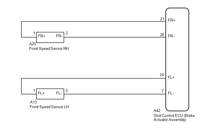
(b) Disconnect the A25 front speed sensor RH connector.
(c) Check both the connector case and the terminals for deformation and corrosion.
OK:
No deformation or corrosion.
(d) Turn the ignition switch to ON.
(e) Measure the voltage according to the value(s) in the table below.
Standard Voltage:
|
Tester Connection |
Condition |
Specified Condition |
|---|---|---|
|
A25-1 (FR+) - Body ground |
Ignition switch ON |
11 to 14 V |
| NG | |
GO TO STEP 7 |
|
|
5. |
INSPECT BRAKE ACTUATOR ASSEMBLY (GROUND CIRCUIT) |
|
(a) Measure the voltage according to the value(s) in the table below. Standard Voltage:
|
|
.png)
| NG | |
GO TO STEP 8 |
|
|
6. |
CHECK FRONT SPEED SENSOR ROTOR (FRONT AXLE HUB ASSEMBLY RH) (CHECK FOR FOREIGN MATTER) |
(a) Remove the front speed sensor rotor (front axle hub assembly RH).
Click here
(b) Check the speed sensor rotor.
OK:
The rotor is free of scratches, oil, and foreign matter.
NOTICE:
- If there is oil or foreign matter on the speed sensor rotor, clean the speed sensor rotor.
- If the speed sensor rotor is damaged, replace the speed sensor rotor with a new one.
- Check the speed sensor signal after cleaning or replacement.
Click here
HINT:
- The front speed sensor rotor is incorporated into the front axle hub assembly.
- If the front speed sensor rotor needs to be replaced, replace it together with the front axle hub assembly.
|
Result |
Proceed to |
|---|---|
|
OK |
A |
|
NG (The speed sensor rotor is damaged.) |
B |
|
NG (There is foreign matter on the speed sensor rotor.) |
C |
| A | |
REPLACE FRONT SPEED SENSOR RH |
| B | |
REPLACE FRONT AXLE HUB SUB-ASSEMBLY RH |
| C | |
CLEAN FRONT SPEED SENSOR ROTOR (FRONT AXLE HUB ASSEMBLY RH) |
|
7. |
CHECK HARNESS AND CONNECTOR (BRAKE ACTUATOR ASSEMBLY - FRONT SPEED SENSOR RH) |
(a) Turn the ignition switch off.
(b) Make sure that there is no looseness at the locking part and the connecting part of the connectors.
OK:
The connector is securely connected.
(c) Disconnect the A42 skid control ECU (brake actuator assembly) connector.
(d) Check both the connector case and the terminals for deformation and corrosion.
OK:
No deformation or corrosion.
(e) Measure the resistance according to the value(s) in the table below.
Standard Resistance:
|
Tester Connection |
Condition |
Specified Condition |
|---|---|---|
|
A42-26 (FR-) - A25-2 (FR-) |
Always |
Below 1 Ω |
|
A42-26 (FR-) or A25-2 (FR-) - Body ground |
Always |
10 kΩ or higher |
| OK | |
REPLACE BRAKE ACTUATOR ASSEMBLY |
| NG | |
REPAIR OR REPLACE HARNESS OR CONNECTOR |
|
8. |
CHECK HARNESS AND CONNECTOR (BRAKE ACTUATOR ASSEMBLY - FRONT SPEED SENSOR RH) |
(a) Turn the ignition switch off.
(b) Make sure that there is no looseness at the locking part and the connecting part of the connectors.
OK:
The connector is securely connected.
(c) Disconnect the A42 skid control ECU (brake actuator assembly) connector.
(d) Check both the connector case and the terminals for deformation and corrosion.
OK:
No deformation or corrosion.
(e) Measure the resistance according to the value(s) in the table below.
Standard Resistance:
|
Tester Connection |
Condition |
Specified Condition |
|---|---|---|
|
A42-26 (FR-) - A25-2 (FR-) |
Always |
Below 1 Ω |
|
A42-26 (FR-) or A25-2 (FR-) - Body ground |
Always |
10 kΩ or higher |
| OK | |
REPLACE BRAKE ACTUATOR ASSEMBLY |
| NG | |
REPAIR OR REPLACE HARNESS OR CONNECTOR |
|
9. |
CHECK FRONT SPEED SENSOR LH INSTALLATION |
|
(a) Turn the ignition switch off. |
|
(b) Check the speed sensor installation.
OK:
There is no clearance between the sensor and the front steering knuckle LH.
The installation bolt is tightened properly.
Torque
8.5 N*m (87 kgf*cm, 75 in.*lbf)
| NG | |
REINSTALL OR REPLACE FRONT SPEED SENSOR LH |
|
|
10. |
CHECK FRONT SPEED SENSOR LH (CHECK FOR FOREIGN MATTER) |
(a) Remove the front speed sensor LH.
Click here
(b) Check the speed sensor tip.
OK:
The sensor tip is free of scratches, oil, and foreign matter.
NOTICE:
- If there is oil or foreign matter on the speed sensor, clean the speed sensor.
- If the speed sensor is damaged, replace the speed sensor with a new one.
- Check the speed sensor signal after cleaning or replacement.
Click here
| NG | |
CLEAN OR REPLACE FRONT SPEED SENSOR LH |
|
|
11. |
INSPECT BRAKE ACTUATOR ASSEMBLY (POWER SOURCE CIRCUIT) |
|
(a) Make sure that there is no looseness at the locking part and the connecting part of the connectors. OK: The connector is securely connected. |
|
.png)
(b) Disconnect the A13 front speed sensor LH connector.
(c) Check both the connector case and the terminals for deformation and corrosion.
OK:
No deformation or corrosion.
(d) Turn the ignition switch to ON.
(e) Measure the voltage according to the value(s) in the table below.
Standard Voltage:
|
Tester Connection |
Condition |
Specified Condition |
|---|---|---|
|
A13-1 (FL+) - Body ground |
Ignition switch ON |
11 to 14 V |
| NG | |
GO TO STEP 14 |
|
|
12. |
INSPECT BRAKE ACTUATOR ASSEMBLY (GROUND CIRCUIT) |
|
(a) Measure the voltage according to the value(s) in the table below. Standard Voltage:
|
|
.png)
| NG | |
GO TO STEP 15 |
|
|
13. |
CHECK FRONT SPEED SENSOR ROTOR (FRONT AXLE HUB ASSEMBLY LH) (CHECK FOR FOREIGN MATTER) |
(a) Remove the front speed sensor rotor (front axle hub assembly LH).
Click here
(b) Check the speed sensor rotor.
OK:
The rotor is free of scratches, oil, and foreign matter.
NOTICE:
- If there is oil or foreign matter on the speed sensor rotor, clean the speed sensor rotor.
- If the speed sensor rotor is damaged, replace the speed sensor rotor with a new one.
- Check the speed sensor signal after cleaning or replacement.
Click here
HINT:
- The front speed sensor rotor is incorporated into the front axle hub assembly.
- If the front speed sensor rotor needs to be replaced, replace it together with the front axle hub assembly.
|
Result |
Proceed to |
|---|---|
|
OK |
A |
|
NG (The speed sensor rotor is damaged.) |
B |
|
NG (There is foreign matter on the speed sensor rotor.) |
C |
| A | |
REPLACE FRONT SPEED SENSOR LH |
| B | |
REPLACE FRONT AXLE HUB SUB-ASSEMBLY LH |
| C | |
CLEAN FRONT SPEED SENSOR ROTOR (FRONT AXLE HUB ASSEMBLY RH) |
|
14. |
CHECK HARNESS AND CONNECTOR (BRAKE ACTUATOR ASSEMBLY - FRONT SPEED SENSOR LH) |
(a) Turn the ignition switch off.
(b) Make sure that there is no looseness at the locking part and the connecting part of the connectors.
OK:
The connector is securely connected.
(c) Disconnect the A42 skid control ECU (brake actuator assembly) connector.
(d) Check both the connector case and the terminals for deformation and corrosion.
OK:
No deformation or corrosion.
(e) Measure the resistance according to the value(s) in the table below.
Standard Resistance:
|
Tester Connection |
Condition |
Specified Condition |
|---|---|---|
|
A42-7 (FL-) - A13-2 (FL-) |
Always |
Below 1 Ω |
|
A42-7 (FL-) or A13-2 (FR-) - Body ground |
Always |
10 kΩ or higher |
| OK | |
REPLACE BRAKE ACTUATOR ASSEMBLY |
| NG | |
REPAIR OR REPLACE HARNESS OR CONNECTOR |
|
15. |
CHECK HARNESS AND CONNECTOR (BRAKE ACTUATOR ASSEMBLY - FRONT SPEED SENSOR LH) |
(a) Turn the ignition switch off.
(b) Make sure that there is no looseness at the locking part and the connecting part of the connectors.
OK:
The connector is securely connected.
(c) Disconnect the A42 skid control ECU (brake actuator assembly) connector.
(d) Check both the connector case and the terminals for deformation and corrosion.
OK:
No deformation or corrosion.
(e) Measure the resistance according to the value(s) in the table below.
Standard Resistance:
|
Tester Connection |
Condition |
Specified Condition |
|---|---|---|
|
A42-7 (FL-) - A13-2 (FL-) |
Always |
Below 1 Ω |
|
A42-7 (FL-) or A13-2 (FR-) - Body ground |
Always |
10 kΩ or higher |
| OK | |
REPLACE BRAKE ACTUATOR ASSEMBLY |
| NG | |
REPAIR OR REPLACE HARNESS OR CONNECTOR |
|
16. |
CHECK REAR SPEED SENSOR RH INSTALLATION |
|
(a) Turn the ignition switch off. |
|
.png)
(b) Check the speed sensor installation.
OK:
There is no clearance between the sensor and the rear axle hub.
HINT:
Because the rear axle hub and bearing assembly RH cannot be disassembled, if the rear speed sensor needs replacement, replace the rear axle hub and bearing assembly RH.
| NG | |
REPLACE REAR AXLE HUB AND BEARING ASSEMBLY RH |
|
|
17. |
INSPECT BRAKE ACTUATOR ASSEMBLY (POWER SOURCE CIRCUIT) |
|
(a) Make sure that there is no looseness at the locking part and the connecting part of the connectors. OK: The connector is securely connected. |
|
.png)
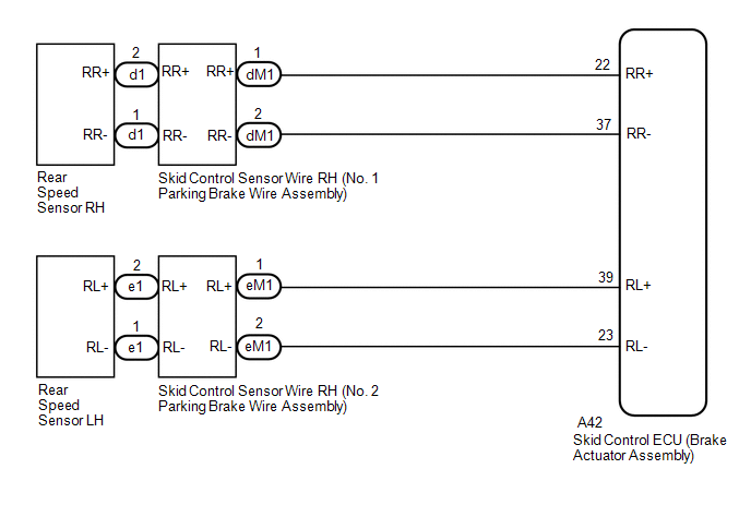
(b) Disconnect the d1 rear speed sensor RH connector.
(c) Check both the connector case and the terminals for deformation and corrosion.
OK:
No deformation or corrosion.
(d) Turn the ignition switch to ON.
(e) Measure the voltage according to the value(s) in the table below.
Standard Voltage:
|
Tester Connection |
Condition |
Specified Condition |
|---|---|---|
|
d1-2 (RR+) - Body ground |
Ignition switch ON |
11 to 14 V |
| NG | |
GO TO STEP 19 |
|
|
18. |
INSPECT BRAKE ACTUATOR ASSEMBLY (GROUND CIRCUIT) |
|
(a) Measure the voltage according to the value(s) in the table below. Standard Voltage:
|
|
.png)
| OK | |
REPLACE REAR AXLE HUB AND BEARING ASSEMBLY RH |
| NG | |
GO TO STEP 21 |
|
19. |
INSPECT SKID CONTROL SENSOR WIRE RH (NO. 1 PARKING BRAKE WIRE ASSEMBLY) |
|
(a) Turn the ignition switch off. |
|
.png)
(b) Make sure that there is no looseness at the locking part and the connecting part of the connectors.
OK:
The connector is securely connected.
(c) Remove the skid control sensor wire RH (No. 1 parking brake wire assembly).
(d) Check both the connector case and the terminals for deformation and corrosion.
OK:
No deformation or corrosion.
(e) Measure the resistance according to the value(s) in the table below.
Standard Resistance:
|
Tester Connection |
Condition |
Specified Condition |
|---|---|---|
|
d1-1 (RR-) - dM1-2 (RR-) |
Always |
Below 1 Ω |
|
d1-1 (RR-) - dM1-1 (RR+) |
Always |
10 kΩ or higher |
|
d1-1 (RR-) or dM1-2 (RR-) - Body ground |
Always |
10 kΩ or higher |
NOTICE:
Check the speed sensor signal after replacement.
Click here
| NG | |
REPLACE SKID CONTROL SENSOR WIRE RH (NO. 1 PARKING BRAKE WIRE ASSEMBLY) |
|
|
20. |
CHECK HARNESS AND CONNECTOR (BRAKE ACTUATOR ASSEMBLY - SKID CONTROL SENSOR WIRE RH (NO. 1 PARKING BRAKE WIRE ASSEMBLY)) |
(a) Make sure that there is no looseness at the locking part and the connecting part of the connector.
OK:
The connector is securely connected.
(b) Disconnect the A42 skid control ECU (brake actuator assembly) connector.
(c) Check both the connector case and the terminals for deformation and corrosion.
OK:
No deformation or corrosion.
(d) Measure the resistance according to the value(s) in the table below.
Standard Resistance:
|
Tester Connection |
Condition |
Specified Condition |
|---|---|---|
|
A42-37 (RR-) - dM1-2 (RR-) |
Always |
Below 1 Ω |
|
A42-37 (RR-) or dM1-2 (RR-) - Body ground |
Always |
10 kΩ or higher |
| OK | |
REPLACE BRAKE ACTUATOR ASSEMBLY |
| NG | |
REPAIR OR REPLACE HARNESS OR CONNECTOR |
|
21. |
INSPECT SKID CONTROL SENSOR WIRE RH (NO. 1 PARKING BRAKE WIRE ASSEMBLY) |
|
(a) Turn the ignition switch off. |
|
(b) Make sure that there is no looseness at the locking part and the connecting part of the connectors.
OK:
The connector is securely connected.
(c) Remove the skid control sensor wire RH (No. 1 parking brake wire assembly).
(d) Check both the connector case and the terminals for deformation and corrosion.
OK:
No deformation or corrosion.
(e) Measure the resistance according to the value(s) in the table below.
Standard Resistance:
|
Tester Connection |
Condition |
Specified Condition |
|---|---|---|
|
d1-1 (RR-) - dM1-2 (RR-) |
Always |
Below 1 Ω |
|
d1-1 (RR-) - dM1-1 (RR+) |
Always |
10 kΩ or higher |
|
d1-1 (RR-) or dM1-2 (RR-) - Body ground |
Always |
10 kΩ or higher |
NOTICE:
Check the speed sensor signal after replacement.
Click here
| NG | |
REPLACE SKID CONTROL SENSOR WIRE RH (NO. 1 PARKING BRAKE WIRE ASSEMBLY) |
|
|
22. |
CHECK HARNESS AND CONNECTOR (BRAKE ACTUATOR ASSEMBLY - SKID CONTROL SENSOR WIRE RH (NO. 1 PARKING BRAKE WIRE ASSEMBLY)) |
(a) Make sure that there is no looseness at the locking part and the connecting part of the connector.
OK:
The connector is securely connected.
(b) Disconnect the A42 skid control ECU (brake actuator assembly) connector.
(c) Check both the connector case and the terminals for deformation and corrosion.
OK:
No deformation or corrosion.
(d) Measure the resistance according to the value(s) in the table below.
Standard Resistance:
|
Tester Connection |
Condition |
Specified Condition |
|---|---|---|
|
A42-37 (RR-) - dM1-2 (RR-) |
Always |
Below 1 Ω |
|
A42-37 (RR-) or dM1-2 (RR-) - Body ground |
Always |
10 kΩ or higher |
| OK | |
REPLACE BRAKE ACTUATOR ASSEMBLY |
| NG | |
REPAIR OR REPLACE HARNESS OR CONNECTOR |
|
23. |
CHECK REAR SPEED SENSOR LH INSTALLATION |
|
(a) Turn the ignition switch off. |
|
(b) Check the speed sensor installation.
OK:
There is no clearance between the sensor and the rear axle hub.
HINT:
Because the rear axle hub and bearing assembly LH cannot be disassembled, if the rear speed sensor needs replacement, replace the rear axle hub and bearing assembly LH.
| NG | |
REPLACE REAR AXLE HUB AND BEARING ASSEMBLY LH |
|
|
24. |
INSPECT BRAKE ACTUATOR ASSEMBLY (POWER SOURCE CIRCUIT) |
|
(a) Make sure that there is no looseness at the locking part and the connecting part of the connectors. OK: The connector is securely connected. |
|
.png)
(b) Disconnect the e1 rear speed sensor LH connector.
(c) Check both the connector case and the terminals for deformation and corrosion.
OK:
No deformation or corrosion.
(d) Turn the ignition switch to ON.
(e) Measure the voltage according to the value(s) in the table below.
Standard Voltage:
|
Tester Connection |
Condition |
Specified Condition |
|---|---|---|
|
e1-2 (RL+) - Body ground |
Ignition switch ON |
11 to 14 V |
| NG | |
GO TO STEP 26 |
|
|
25. |
INSPECT BRAKE ACTUATOR ASSEMBLY (GROUND CIRCUIT) |
|
(a) Measure the voltage according to the value(s) in the table below. Standard Voltage:
|
|
.png)
| OK | |
REPLACE REAR AXLE HUB AND BEARING ASSEMBLY LH |
| NG | |
GO TO STEP 28 |
|
26. |
INSPECT SKID CONTROL SENSOR WIRE LH (NO. 2 PARKING BRAKE WIRE ASSEMBLY) |
|
(a) Turn the ignition switch off. |
|
.png)
(b) Make sure that there is no looseness at the locking part and the connecting part of the connectors.
OK:
The connector is securely connected.
(c) Remove the skid control sensor wire LH (No. 2 parking brake wire assembly).
(d) Check both the connector case and the terminals for deformation and corrosion.
OK:
No deformation or corrosion.
(e) Measure the resistance according to the value(s) in the table below.
Standard Resistance:
|
Tester Connection |
Condition |
Specified Condition |
|---|---|---|
|
e1-1 (RL-) - eM1-2 (RL-) |
Always |
Below 1 Ω |
|
e1-1 (RL-) - eM1-1 (RL+) |
Always |
10 kΩ or higher |
|
e1-1 (RL-) or eM1-2 (RL-) - Body ground |
Always |
10 kΩ or higher |
NOTICE:
Check the speed sensor signal after replacement.
Click here
| NG | |
REPLACE SKID CONTROL SENSOR WIRE LH (NO. 2 PARKING BRAKE WIRE ASSEMBLY) |
|
|
27. |
CHECK HARNESS AND CONNECTOR (BRAKE ACTUATOR ASSEMBLY - SKID CONTROL SENSOR WIRE LH (NO. 2 PARKING BRAKE WIRE ASSEMBLY)) |
(a) Make sure that there is no looseness at the locking part and the connecting part of the connector.
OK:
The connector is securely connected.
(b) Disconnect the A42 skid control ECU (brake actuator assembly) connector.
(c) Check both the connector case and the terminals for deformation and corrosion.
OK:
No deformation or corrosion.
(d) Measure the resistance according to the value(s) in the table below.
Standard Resistance:
|
Tester Connection |
Condition |
Specified Condition |
|---|---|---|
|
A42-23 (RL-) - eM1-2 (RL-) |
Always |
Below 1 Ω |
|
A42-23 (RL-) or eM1-2 (RL-) - Body ground |
Always |
10 kΩ or higher |
| OK | |
REPLACE BRAKE ACTUATOR ASSEMBLY |
| NG | |
REPAIR OR REPLACE HARNESS OR CONNECTOR |
|
28. |
INSPECT SKID CONTROL SENSOR WIRE LH (NO. 2 PARKING BRAKE WIRE ASSEMBLY) |
|
(a) Turn the ignition switch off. |
|
(b) Make sure that there is no looseness at the locking part and the connecting part of the connectors.
OK:
The connector is securely connected.
(c) Remove the skid control sensor wire LH (No. 2 parking brake wire assembly).
(d) Check both the connector case and the terminals for deformation and corrosion.
OK:
No deformation or corrosion.
(e) Measure the resistance according to the value(s) in the table below.
Standard Resistance:
|
Tester Connection |
Condition |
Specified Condition |
|---|---|---|
|
e1-1 (RL-) - eM1-2 (RL-) |
Always |
Below 1 Ω |
|
e1-1 (RL-) - eM1-1 (RL+) |
Always |
10 kΩ or higher |
|
e1-1 (RL-) or eM1-2 (RL-) - Body ground |
Always |
10 kΩ or higher |
NOTICE:
Check the speed sensor signal after replacement.
Click here
| NG | |
REPLACE SKID CONTROL SENSOR WIRE LH (NO. 2 PARKING BRAKE WIRE ASSEMBLY) |
|
|
29. |
CHECK HARNESS AND CONNECTOR (BRAKE ACTUATOR ASSEMBLY - SKID CONTROL SENSOR WIRE LH (NO. 2 PARKING BRAKE WIRE ASSEMBLY)) |
(a) Make sure that there is no looseness at the locking part and the connecting part of the connector.
OK:
The connector is securely connected.
(b) Disconnect the A42 skid control ECU (brake actuator assembly) connector.
(c) Check both the connector case and the terminals for deformation and corrosion.
OK:
No deformation or corrosion.
(d) Measure the resistance according to the value(s) in the table below.
Standard Resistance:
|
Tester Connection |
Condition |
Specified Condition |
|---|---|---|
|
A42-23 (RL-) - eM1-2 (RL-) |
Always |
Below 1 Ω |
|
A42-23 (RL-) or eM1-2 (RL-) - Body ground |
Always |
10 kΩ or higher |
| OK | |
REPLACE BRAKE ACTUATOR ASSEMBLY |
| NG | |
REPAIR OR REPLACE HARNESS OR CONNECTOR |
 Skid Control ECU Malfunction (C1300)
DESCRIPTION
The skid control ECU (brake actuator assembly) stores this DTC if malfunctions
are found in a circuit inside the ECU by self diagnosis.
DTC No.
Detection Item
...
 Zero Point Calibration of Acceleration Sensor Undone (C1336)
DESCRIPTION
The skid control ECU (brake actuator assembly) receives signals from the yaw
rate and acceleration sensor (airbag sensor assembly) via CAN communication.
The airbag sensor assembly has ...
Other materials:
Toyota CH-R Service Manual > Roof Headlining: Components
COMPONENTS
ILLUSTRATION
*A
w/ Package Tray Trim
*B
w/ Tonneau Cover
*1
PACKAGE TRAY TRIM PANEL ASSEMBLY
*2
TONNEAU COVER ASSEMBLY
ILLUSTRATION
*A
for Type A
...
Toyota CH-R Service Manual > Cellular Communication: Dcm(telematics Transceiver)
Components
COMPONENTS
ILLUSTRATION
*1
DCM (TELEMATICS TRANSCEIVER)
-
-
N*m (kgf*cm, ft.*lbf): Specified torque
-
-
Removal
REMOVAL
CAUTION / NOTICE / HINT
The necessary procedures (adjus ...
Toyota C-HR (AX20) 2023-2026 Owner's Manual
Toyota CH-R Owners Manual
- For safety and security
- Instrument cluster
- Operation of each component
- Driving
- Interior features
- Maintenance and care
- When trouble arises
- Vehicle specifications
- For owners
Toyota CH-R Service Manual
- Introduction
- Maintenance
- Audio / Video
- Cellular Communication
- Navigation / Multi Info Display
- Park Assist / Monitoring
- Brake (front)
- Brake (rear)
- Brake Control / Dynamic Control Systems
- Brake System (other)
- Parking Brake
- Axle And Differential
- Drive Shaft / Propeller Shaft
- K114 Cvt
- 3zr-fae Battery / Charging
- Networking
- Power Distribution
- Power Assist Systems
- Steering Column
- Steering Gear / Linkage
- Alignment / Handling Diagnosis
- Front Suspension
- Rear Suspension
- Tire / Wheel
- Tire Pressure Monitoring
- Door / Hatch
- Exterior Panels / Trim
- Horn
- Lighting (ext)
- Mirror (ext)
- Window / Glass
- Wiper / Washer
- Door Lock
- Heating / Air Conditioning
- Interior Panels / Trim
- Lighting (int)
- Meter / Gauge / Display
- Mirror (int)
- Power Outlets (int)
- Pre-collision
- Seat
- Seat Belt
- Supplemental Restraint Systems
- Theft Deterrent / Keyless Entry

0.0081