Toyota CH-R Service Manual: Precaution
PRECAUTION
IGNITION SWITCH EXPRESSION
HINT:
The type of ignition switch used on this model differs according to the specifications of the vehicle. The expressions listed in the table below are used in this section.
|
Expression |
Ignition Switch (Position) |
Engine Switch (Condition) |
|---|---|---|
|
Ignition Switch off |
LOCK |
Off (Lock) |
|
Ignition Switch ACC |
ACC |
On (ACC) |
|
Ignition Switch ON |
ON |
On (IG) |
|
Engine Start |
START |
On (Start) |
TROUBLESHOOTING PRECAUTION
(a) When there is a malfunction with terminal contact points or part installation problems, removal and installation of the suspected parts may return the system to normal either completely or temporarily.
(b) In order to determine the malfunctioning area, be sure to check the conditions at the time the malfunction occurred, such as DTC output and Freeze Frame Data, and record it before disconnecting any connector or removing and installing parts.
(c) Since the system may be influenced by malfunctions in systems other than the VSC system, be sure to check for DTCs in other systems.
HANDLING PRECAUTION
(a) Do not remove or install VSC parts such as the steering angle sensor or yaw rate and acceleration sensor (airbag sensor assembly) except when required, as they need to be adjusted correctly after removal and installation.
(b) Be sure to perform preparation before work and confirmation after work is completed by following the directions in the repair manual when working on the VSC system.
(c) Be sure to remove and install the skid control ECU (brake actuator assembly), sensors, etc. with the ignition switch off unless it is otherwise specified in the inspection procedure.
(d) If the skid control ECU (brake actuator assembly) or a sensor has been removed and installed, it is necessary to check the system for problems after the parts have been reassembled. Check for DTCs using the Techstream. Also check that the system functions and signals received by the ECU are normal using Test Mode.
DTC PRECAUTION
(a) Warnings for some DTCs cannot be cleared only by repairing the malfunctioning parts. If the warning is displayed after repair work, the DTC should be cleared after turning the ignition switch off.
NOTICE:
If a DTC for a malfunctioning part reappears after it was cleared, then it has been stored again.
(b) When 2 or more DTCs are detected, perform diagnosis for each DTC, one by one until the problem is identified.
CHASSIS DYNAMOMETER PRECAUTION
When testing with a 2-wheel drum tester such as speedometer tester, combination tester for the speedometer and brakes, or chassis dynamometer, or when jacking up the front wheels and turning the wheels, perform the following procedure to enter Inspection Mode and disable the TRAC and VSC systems.
CAUTION:
- Do not use the drum tester with any of the lock chains disconnected.
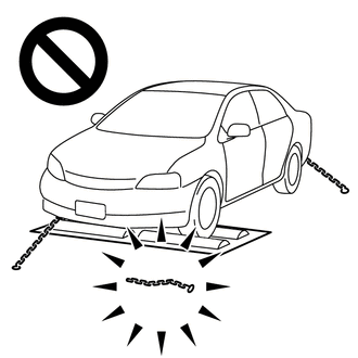
- Using the drum tester with a lock chain disconnected could cause the vehicle to begin moving unexpectedly.
- Do not use the drum tester while the TRAC or VSC is able to operate.
- TRAC or VSC operation could cause the vehicle to begin moving unexpectedly.
NOTICE:
Secure the vehicle with lock chains for safety.
(a) Activating Inspection Mode (When Using the Techstream)
(1) Ensure that the ignition switch is off and the engine is stopped.
(2) Make sure that the shift lever is in P.
(3) Connect the Techstream to the DLC3.
(4) Start the engine.
(5) Turn the Techstream on.
(6) Enter the following menus: Chassis / ABS/VSC/TRAC/EPB / Utility / Inspection Mode.
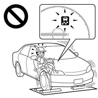
(7) Check that the VSC OFF indicator light comes on and the TRAC OFF message is displayed on the multi-information display.
HINT:
- If the VSC OFF indicator light does not come on and the TRAC OFF message is not displayed on the multi-information display repeat the steps.
- Turning the ignition switch off ends Inspection Mode.
(b) Activating Inspection Mode (When Using the SST Check Wire)
HINT:
Perform steps "C" to "H" within 30 seconds.
(1) Ensure that the ignition switch is off and the engine is stopped (Step "A").
(2) Make sure that the shift lever is in P (Step "B").
(3) Start the engine (Step "C").
(4) Apply the parking brake (Step "D").
(5) Depress and release the brake pedal twice (Step "E").
(6) While holding the brake pedal down, release and apply the parking brake twice (Step "F").
(7) With the parking brake applied, depress and release the brake pedal twice (Step "G").
(8) Check that the VSC OFF indicator light comes on and the TRAC OFF message is displayed on the multi-information display (Step "H").
HINT:
- If the VSC OFF indicator light comes on and the TRAC OFF message is displayed on the multi-information display in step "H", repeat steps "A" to "H".
- Turning the ignition switch off ends Inspection Mode.
CAN COMMUNICATION SYSTEM PRECAUTION
(a) The CAN communication system is used for communication between the skid control ECU (brake actuator assembly), steering angle sensor, yaw rate and acceleration sensor (airbag sensor assembly) and other ECUs. If there is trouble in the CAN communication line, corresponding DTCs in the communication line are output.
(b) If any CAN communication DTCs are output, repair the malfunction, then troubleshoot the VSC system while communication is normal.
(c) In order to enable CAN communication, a specific type of wiring is used for the CAN communication lines. The wiring used for each communication line is a twisted pair of wires that have an equal length. A bypass wire should not be used because the data being transmitted will be corrupted.

 Parts Location
PARTS LOCATION
ILLUSTRATION
*1
FRONT AXLE HUB ASSEMBLY RH
- FRONT SPEED SENSOR ROTOR RH
*2
FRONT SPEED SENSOR RH
*3
FRONT ...
Other materials:
Toyota CH-R Service Manual > Back Door Lock: Installation
INSTALLATION
PROCEDURE
1. INSTALL BACK DOOR LOCK ASSEMBLY
HINT:
Make sure to remove the string before installing a new back door lock assembly.
(a) Apply MP grease to the sliding parts of the back door lock assembly.
(b) Install the back door lock assembly with the 3 bolts.
Torque:
7.5 N·m ...
Toyota CH-R Service Manual > Vacuum Pump: Disassembly
DISASSEMBLY
PROCEDURE
1. REMOVE END COVER
(a) Using a T25 "TORX" socket wrench, remove the 5 screws and end cover.
NOTICE:
Hold the vacuum pump assembly so that its installation surface,
fitting parts and oil pipe will not be damaged.
As the vac ...
Toyota C-HR (AX20) 2023-2026 Owner's Manual
Toyota CH-R Owners Manual
- For safety and security
- Instrument cluster
- Operation of each component
- Driving
- Interior features
- Maintenance and care
- When trouble arises
- Vehicle specifications
- For owners
Toyota CH-R Service Manual
- Introduction
- Maintenance
- Audio / Video
- Cellular Communication
- Navigation / Multi Info Display
- Park Assist / Monitoring
- Brake (front)
- Brake (rear)
- Brake Control / Dynamic Control Systems
- Brake System (other)
- Parking Brake
- Axle And Differential
- Drive Shaft / Propeller Shaft
- K114 Cvt
- 3zr-fae Battery / Charging
- Networking
- Power Distribution
- Power Assist Systems
- Steering Column
- Steering Gear / Linkage
- Alignment / Handling Diagnosis
- Front Suspension
- Rear Suspension
- Tire / Wheel
- Tire Pressure Monitoring
- Door / Hatch
- Exterior Panels / Trim
- Horn
- Lighting (ext)
- Mirror (ext)
- Window / Glass
- Wiper / Washer
- Door Lock
- Heating / Air Conditioning
- Interior Panels / Trim
- Lighting (int)
- Meter / Gauge / Display
- Mirror (int)
- Power Outlets (int)
- Pre-collision
- Seat
- Seat Belt
- Supplemental Restraint Systems
- Theft Deterrent / Keyless Entry

0.0096