Toyota CH-R Service Manual: Components
COMPONENTS
ILLUSTRATION
|
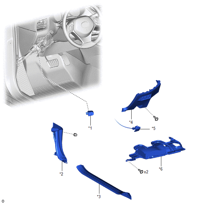
*1 |
BLIND SPOT MONITOR BUZZER |
*2 |
COWL SIDE TRIM BOARD LH |
|
*3 |
FRONT DOOR SCUFF PLATE LH |
*4 |
FUSE BOX OPENING COVER |
|
*5 |
HOOD LOCK CONTROL LEVER SUB-ASSEMBLY |
*6 |
NO. 1 INSTRUMENT PANEL UNDER COVER SUB-ASSEMBLY |

 Removal
REMOVAL
CAUTION / NOTICE / HINT
The necessary procedures (adjustment, calibration, initialization, or registration)
that must be performed after parts are removed and installed, or replaced during ...
Other materials:
Toyota CH-R Service Manual > Air Conditioning Pressure Sensor: Removal
REMOVAL
PROCEDURE
1. RECOVER REFRIGERANT FROM REFRIGERATION SYSTEM (for HFC-134a(R134a))
Click here
2. RECOVER REFRIGERANT FROM REFRIGERATION SYSTEM (for HFO-1234yf(R1234yf))
Click here
3. REMOVE AIR CONDITIONER PRESSURE SENSOR (for VALEO Made)
(a) Disconnect the connector.
...
Toyota CH-R Service Manual > Rear Suspension Member: Installation
INSTALLATION
PROCEDURE
1. INSTALL HOLE PLUG
(a) Install the 7 hole plugs to the rear suspension member sub-assembly as shown
in the illustration.
2. INSTALL REAR SUSPENSION MEMBER HOLE COVER
(a) Install the 4 rear suspension member hole covers to the rear suspension member
sub-assembly.
3. ...
Toyota C-HR (AX20) 2023-2026 Owner's Manual
Toyota CH-R Owners Manual
- For safety and security
- Instrument cluster
- Operation of each component
- Driving
- Interior features
- Maintenance and care
- When trouble arises
- Vehicle specifications
- For owners
Toyota CH-R Service Manual
- Introduction
- Maintenance
- Audio / Video
- Cellular Communication
- Navigation / Multi Info Display
- Park Assist / Monitoring
- Brake (front)
- Brake (rear)
- Brake Control / Dynamic Control Systems
- Brake System (other)
- Parking Brake
- Axle And Differential
- Drive Shaft / Propeller Shaft
- K114 Cvt
- 3zr-fae Battery / Charging
- Networking
- Power Distribution
- Power Assist Systems
- Steering Column
- Steering Gear / Linkage
- Alignment / Handling Diagnosis
- Front Suspension
- Rear Suspension
- Tire / Wheel
- Tire Pressure Monitoring
- Door / Hatch
- Exterior Panels / Trim
- Horn
- Lighting (ext)
- Mirror (ext)
- Window / Glass
- Wiper / Washer
- Door Lock
- Heating / Air Conditioning
- Interior Panels / Trim
- Lighting (int)
- Meter / Gauge / Display
- Mirror (int)
- Power Outlets (int)
- Pre-collision
- Seat
- Seat Belt
- Supplemental Restraint Systems
- Theft Deterrent / Keyless Entry

0.0091