Toyota CH-R Service Manual: GPS Antenna Connection Malfunction(short) (B15C0,B15C1)
DESCRIPTION
These DTCs are stored when a malfunction occurs in the navigation antenna assembly.
|
DTC No. |
Detection Item |
DTC Detection Condition |
Trouble Area |
|---|---|---|---|
|
B15C0 |
GPS Antenna Connection Malfunction(short) |
Navigation antenna malfunction |
|
|
B15C1 |
GPS Antenna Connection Malfunction(break) |
Navigation antenna power source malfunction |
|
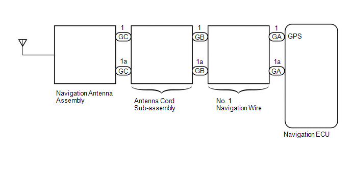
WIRING DIAGRAM
CAUTION / NOTICE / HINT
NOTICE:
- Depending on the parts that are replaced during vehicle inspection or
maintenance, performing initialization, registration or calibration may
be needed. Refer to Precaution for Navigation System.
Click here
.gif)
- When replacing the navigation ECU, always replace it with a new one.
If a navigation ECU which was installed to another vehicle is used, the
following may occur:
- A communication malfunction DTC is stored.
- The radio and display receiver assembly may not operate normally.
- Check that the antenna cord sub-assembly is properly installed and does
not have any sharp bends, pinching or loose connections before performing
following procedure.
Click here
PROCEDURE
|
1. |
CHECK DTC |
(a) Clear the DTCs.
Body Electrical > Navigation System > Clear DTCs(b) Recheck for DTCs and check that no DTCs are output.
Body Electrical > Navigation System > Trouble CodesOK:
No DTCs are output.
| OK | .gif) |
USE SIMULATION METHOD TO CHECK |
|
.gif)
|
2. |
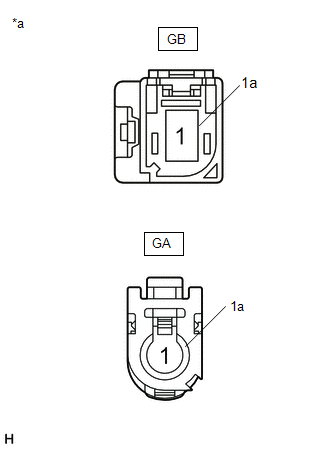
INSPECT NO. 1 NAVIGATION WIRE |
(a) Remove the No. 1 navigation wire.
Click here
|
(b) Measure the resistance according to the value(s) in the table below. Standard Resistance:
|
|
| NG | |
REPLACE NO. 1 NAVIGATION WIRE |
|
|
3. |
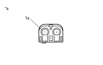
INSPECT NAVIGATION ANTENNA ASSEMBLY |
(a) Remove the navigation antenna assembly.
Click here
|
(b) Measure the resistance according to the value(s) in the table below. Standard Resistance:
|
|
| NG | |
REPLACE NAVIGATION ANTENNA ASSEMBLY |
|
|
4. |
REPLACE ANTENNA CORD SUB-ASSEMBLY |
(a) Replace the antenna cord sub-assembly with a new or known good one.
Click here
|
|
5. |
CHECK DTC |
(a) Clear the DTCs.
Body Electrical > Navigation System > Clear DTCs(b) Recheck for DTCs and check that no DTCs are output.
Body Electrical > Navigation System > Trouble CodesOK:
No DTCs are output.
| OK | |
END (ANTENNA CORD SUB-ASSEMBLY IS DEFECTIVE) |
| NG | |
REPLACE NAVIGATION ECU |
 Speed Signal Malfunction (B15C2)
DESCRIPTION
The navigation ECU receives a vehicle speed signal from the combination meter
assembly and information from the navigation antenna assembly, and then adjusts
the vehicle position on t ...
 Navigation Processor Malfunction (B15AD)
DESCRIPTION
These DTCs are stored when a malfunction occurs in the navigation ECU.
DTC No.
Detection Item
DTC Detection Condition
Trouble Area
...
Other materials:
Toyota CH-R Service Manual > Rear Bumper: Installation
INSTALLATION
PROCEDURE
1. INSTALL REAR BUMPER ASSEMBLY
(a) Engage the claws as shown in the illustration.
Install in the Direction
(b) Engage the claws to install the rear bumper assembly as shown in the illustration.
HINT:
Use the same procedure for the RH side ...
Toyota CH-R Service Manual > Smart Key System(for Start Function): Dtc Check / Clear
DTC CHECK / CLEAR
NOTICE:
When using the Techstream with the engine switch off, connect the Techstream
to the DLC3 and turn a courtesy light switch on and off at intervals of 1.5 seconds
or less until communication between the Techstream and the vehicle begins. Then
select the vehicle type u ...
Toyota C-HR (AX20) 2023-2026 Owner's Manual
Toyota CH-R Owners Manual
- For safety and security
- Instrument cluster
- Operation of each component
- Driving
- Interior features
- Maintenance and care
- When trouble arises
- Vehicle specifications
- For owners
Toyota CH-R Service Manual
- Introduction
- Maintenance
- Audio / Video
- Cellular Communication
- Navigation / Multi Info Display
- Park Assist / Monitoring
- Brake (front)
- Brake (rear)
- Brake Control / Dynamic Control Systems
- Brake System (other)
- Parking Brake
- Axle And Differential
- Drive Shaft / Propeller Shaft
- K114 Cvt
- 3zr-fae Battery / Charging
- Networking
- Power Distribution
- Power Assist Systems
- Steering Column
- Steering Gear / Linkage
- Alignment / Handling Diagnosis
- Front Suspension
- Rear Suspension
- Tire / Wheel
- Tire Pressure Monitoring
- Door / Hatch
- Exterior Panels / Trim
- Horn
- Lighting (ext)
- Mirror (ext)
- Window / Glass
- Wiper / Washer
- Door Lock
- Heating / Air Conditioning
- Interior Panels / Trim
- Lighting (int)
- Meter / Gauge / Display
- Mirror (int)
- Power Outlets (int)
- Pre-collision
- Seat
- Seat Belt
- Supplemental Restraint Systems
- Theft Deterrent / Keyless Entry

0.0091