Toyota CH-R Service Manual: Speed Signal Malfunction (B15C2)
DESCRIPTION
The navigation ECU receives a vehicle speed signal from the combination meter assembly and information from the navigation antenna assembly, and then adjusts the vehicle position on the map.
The navigation ECU stores this DTC when the difference between the speed information that the navigation antenna assembly receives and the SPD pulse received from the combination meter assembly becomes large.
HINT:
- A voltage of 12 V or 5 V is output from each ECU and then input to the combination meter assembly. The signal is changed to a pulse signal at the transistor in the combination meter assembly. Each ECU controls its respective system based on this pulse signal.
- If a short occurs in any of the ECUs or in the wire harness connected to an ECU, all systems in the following diagram will not operate normally.
|
DTC No. |
Detection Item |
DTC Detection Condition |
Trouble Area |
|---|---|---|---|
|
B15C2 |
Speed Signal Malfunction |
A difference between the GPS speed and SPD pulse is detected |
|
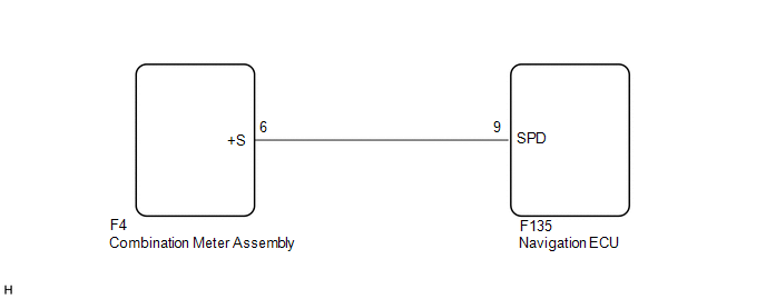
WIRING DIAGRAM
CAUTION / NOTICE / HINT
NOTICE:
- Depending on the parts that are replaced during vehicle inspection or
maintenance, performing initialization, registration or calibration may
be needed. Refer to Precaution for Navigation System.
Click here
.gif)
- When replacing the radio and display receiver assembly or navigation
ECU, always replace it with a new one. If a radio and display receiver assembly
or navigation ECU which was installed to another vehicle is used, the following
may occur:
- A communication malfunction DTC may be stored.
- The radio and display receiver assembly or navigation ECU may not operate normally.
PROCEDURE
|
1. |
CHECK DTC |
(a) Clear the DTCs.
Body Electrical > Navigation System > Clear DTCs(b) Recheck for DTCs and check that no DTCs are output.
Body Electrical > Navigation System > Trouble CodesOK:
No DTCs are output.
| OK | .gif) |
USE SIMULATION METHOD TO CHECK |
|
.gif)
|
2. |
CHECK VEHICLE SENSOR (OPERATION CHECK) |
|
(a) Enter the "System Sensors Check" screen. Refer to Check GPS & Vehicle Sensors in Operation Check. Click here
|
|
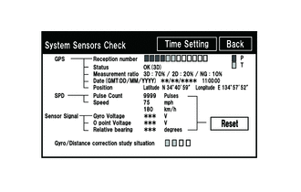
(b) While driving the vehicle, compare the value of "Speed" to the reading on the speedometer. Check if these readings are almost equal.
HINT:
The combination meter assembly receives the vehicle speed signal from the skid control ECU via CAN communication. Therefore, perform the following procedure inspection referring to values in the Data List of the skid control ECU because it is the source of the vehicle speed signal.
OK:
Vehicle speed displayed on the "System Sensors Check" screen is almost the same as the actual vehicle speed measured using the Techstream.
Click here
| OK | |
GO TO STEP 5 |
|
|
3. |
CHECK COMBINATION METER ASSEMBLY (OUTPUT WAVEFORM) |
|
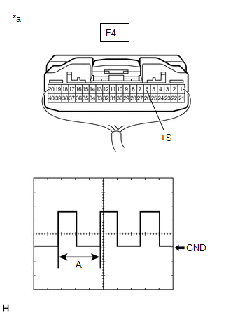
(a) Check the output waveform. (1) Remove the combination meter assembly with the connector(s) still connected. (2) Connect an oscilloscope to terminal F4-6 (+S) and body ground. (3) Turn the engine switch on (IG). (4) Turn a wheel slowly. (5) Check the signal waveform according to the condition(s) in the table below.
OK: The waveform is similar to that shown in the illustration. HINT: When the system is functioning normally, one wheel revolution generates 4 pulses. As the vehicle speed increases, the width indicated by (A) in the illustration narrows. |
|
| NG | |
GO TO METER / GAUGE SYSTEM |
|
|
4. |
CHECK HARNESS AND CONNECTOR (NAVIGATION ECU - COMBINATION METER ASSEMBLY) |
(a) Disconnect the F135 navigation ECU connector.
(b) Disconnect the F4 combination meter assembly connector.
(c) Measure the resistance according to the value(s) in the table below.
Standard Resistance:
|
Tester Connection |
Condition |
Specified Condition |
|---|---|---|
|
F135-9 (SPD) - F4-6 (+S) |
Always |
Below 1 Ω |
|
F135-9 (SPD) or F4-6 (+S) - Body ground |
Always |
10 kΩ or higher |
| NG | |
REPAIR OR REPLACE HARNESS OR CONNECTOR |
|
|
5. |
REPLACE NAVIGATION ECU |
(a) Replace the navigation ECU with a new one.
Click here
|
|
6. |
CHECK DTC |
(a) Clear the DTCs.
Body Electrical > Navigation System > Clear DTCs(b) Recheck for DTCs and check that no DTCs are output.
Body Electrical > Navigation System > Trouble CodesOK:
No DTCs are output.
| OK | |
END (NAVIGATION ECU IS DEFECTIVE) |
| NG | |
REPLACE RADIO AND DISPLAY RECEIVER ASSEMBLY |
 Telematics Transceiver Disconnected (B15DB)
DESCRIPTION
If the radio and display receiver assembly cannot detect the DCM (telematics
transceiver) for a certain period of time (90 seconds) after the engine switch is
turned on (ACC) and the ...
 GPS Antenna Connection Malfunction(short) (B15C0,B15C1)
DESCRIPTION
These DTCs are stored when a malfunction occurs in the navigation antenna assembly.
DTC No.
Detection Item
DTC Detection Condition
Trouble Are ...
Other materials:
Toyota CH-R Service Manual > Continuously Variable Transaxle System: Shift Solenoid "G" Control Circuit Low (Shift Solenoid Valve SC) (P099B,P099C)
DESCRIPTION
Based on the signal received by the shift solenoid valve SC, the ECM uses the
shift solenoid valve SLU to control the forward and reverse clutch pressure.
If there is an open or short in the shift solenoid valve SC circuit, the ECM
stops sending current to the defective shift solen ...
Toyota CH-R Service Manual > Air Conditioning System(for Automatic Air Conditioning System With Side-mounted
Air Conditioner Pressure Sensor): Precaution
PRECAUTION
IGNITION SWITCH EXPRESSIONS
(a) The type of ignition switch used on this model differs according to the specifications
of the vehicle. The expressions listed in the table below are used in this section.
Expression
Ignition Switch (Position)
Engine Swi ...
Toyota C-HR (AX20) 2023-2026 Owner's Manual
Toyota CH-R Owners Manual
- For safety and security
- Instrument cluster
- Operation of each component
- Driving
- Interior features
- Maintenance and care
- When trouble arises
- Vehicle specifications
- For owners
Toyota CH-R Service Manual
- Introduction
- Maintenance
- Audio / Video
- Cellular Communication
- Navigation / Multi Info Display
- Park Assist / Monitoring
- Brake (front)
- Brake (rear)
- Brake Control / Dynamic Control Systems
- Brake System (other)
- Parking Brake
- Axle And Differential
- Drive Shaft / Propeller Shaft
- K114 Cvt
- 3zr-fae Battery / Charging
- Networking
- Power Distribution
- Power Assist Systems
- Steering Column
- Steering Gear / Linkage
- Alignment / Handling Diagnosis
- Front Suspension
- Rear Suspension
- Tire / Wheel
- Tire Pressure Monitoring
- Door / Hatch
- Exterior Panels / Trim
- Horn
- Lighting (ext)
- Mirror (ext)
- Window / Glass
- Wiper / Washer
- Door Lock
- Heating / Air Conditioning
- Interior Panels / Trim
- Lighting (int)
- Meter / Gauge / Display
- Mirror (int)
- Power Outlets (int)
- Pre-collision
- Seat
- Seat Belt
- Supplemental Restraint Systems
- Theft Deterrent / Keyless Entry

0.009