Toyota CH-R Service Manual: Telematics Transceiver Disconnected (B15DB)
DESCRIPTION
If the radio and display receiver assembly cannot detect the DCM (telematics transceiver) for a certain period of time (90 seconds) after the engine switch is turned on (ACC) and the radio and display receiver assembly confirms that the information is missing by checking past DCM (telematics transceiver) recognition information (registered information), this DTC will be stored.
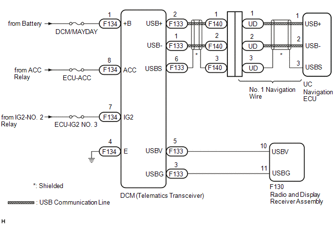
The telematics system uses USB communication between devices. If an open, short, short to +B or short to ground occurs in the USB circuit, communication is interrupted and the telematics system will not operate normally.
|
DTC No. |
Detection Item |
DTC Detection Condition |
Trouble Area |
|---|---|---|---|
|
B15DB |
Telematics Transceiver Disconnected |
DCM (telematics transceiver) disconnected |
|
HINT:
This DTC may be stored due to environmental reasons such as electrical noise or interference.
WIRING DIAGRAM
CAUTION / NOTICE / HINT
NOTICE:
- Depending on the parts that are replaced during vehicle inspection or
maintenance, performing initialization, registration or calibration may
be needed. Refer to Precaution for Navigation System.
Click here
.gif)
- When replacing the radio and display receiver assembly or navigation
ECU, always replace it with a new one. If a radio and display receiver assembly
or navigation ECU which was installed to another vehicle is used, the following
may occur:
- A communication malfunction DTC may be stored.
- The radio and display receiver assembly or navigation ECU may not operate normally.
- Inspect the fuses for circuits related to this system before performing the following procedure.
PROCEDURE
|
1. |
CHECK DTC |
(a) Clear the DTCs.
Body Electrical > Navigation System > Clear DTCs(b) Turn the engine switch off.
(c) Turn the engine switch on (IG) and wait for 90 seconds.
(d) Recheck for DTCs and check that no DTCs are output.
Body Electrical > Navigation System > Trouble CodesOK:
No DTCs are output.
| OK | .gif) |
USE SIMULATION METHOD TO CHECK |
|
.gif)
|
2. |
CHECK HARNESS AND CONNECTOR (DCM (TELEMATICS TRANSCEIVER) POWER SOURCE) |
|
(a) Disconnect the DCM (telematics transceiver) connector. |
|
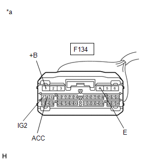
(b) Measure the resistance according to the value(s) in the table below.
Standard Resistance:
|
Tester Connection |
Condition |
Specified Condition |
|---|---|---|
|
F134-4 (E) - Body ground |
Always |
Below 1 Ω |
(c) Measure the voltage according to the value(s) in the table below.
Standard Voltage:
|
Tester Connection |
Condition |
Specified Condition |
|---|---|---|
|
F134-1 (+B) - F134-4 (E) |
Always |
11 to 14 V |
|
F134-8 (ACC) - F134-4 (E) |
Engine switch on (ACC) |
11 to 14 V |
|
F134-7 (IG2) - F134-4 (E) |
Engine switch on (IG) |
11 to 14 V |
| NG | |
REPAIR OR REPLACE HARNESS OR CONNECTOR |
|
|
3. |
CHECK HARNESS AND CONNECTOR (RADIO AND DISPLAY RECEIVER ASSEMBLY - DCM (TELEMATICS TRANSCEIVER)) |
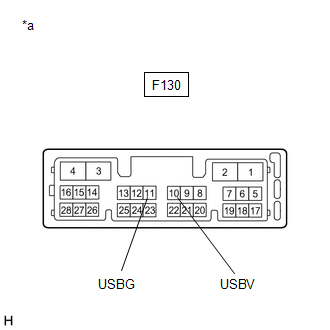
(a) Disconnect the F130 radio and display receiver assembly connector.
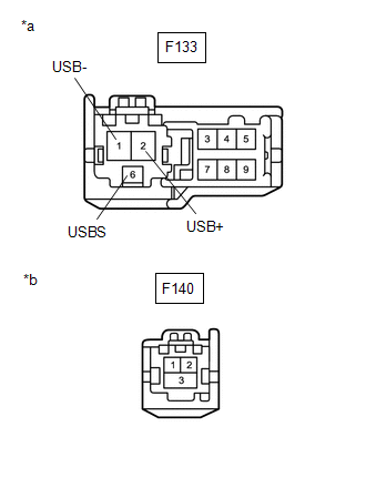
(b) Disconnect the F133 DCM (telematics transceiver) connector.
(c) Measure the resistance according to the value(s) in the table below.
Standard Resistance:
|
Tester Connection |
Condition |
Specified Condition |
|---|---|---|
|
F130-10 (USBV) - F133-5 (USBV) |
Always |
Below 1 Ω |
|
F130-11 (USBG) - F133-3 (USBG) |
Always |
Below 1 Ω |
|
F130-10 (USBV) or F133-5 (USBV) - Body ground |
Always |
10 kΩ or higher |
|
F130-11 (USBG) or F133-3 (USBG) - Body ground |
Always |
10 kΩ or higher |
| NG | |
REPAIR OR REPLACE HARNESS OR CONNECTOR |
|
|
4. |
INSPECT RADIO AND DISPLAY RECEIVER ASSEMBLY |
(a) Disconnect the radio and display receiver assembly connector.
|
(b) Measure the resistance according to the value(s) in the table below. Standard Resistance:
|
|
(c) Measure the voltage according to the value(s) in the table below.
Standard Voltage:
|
Tester Connection |
Condition |
Specified Condition |
|---|---|---|
|
F130-10 (USBV) - F130-11 (USBG) |
Engine switch on (ACC) |
4.75 to 5.25 V |
| NG | |
REPLACE RADIO AND DISPLAY RECEIVER ASSEMBLY |
|
|
5. |
CHECK HARNESS AND CONNECTOR (DCM (TELEMATICS TRANSCEIVER) - NO. 1 NAVIGATION WIRE) |
(a) Disconnect the F133 DCM (telematics transceiver) connector.
(b) Disconnect the F140 No. 1 navigation wire connector.
|
(c) Measure the resistance according to the value(s) in the table below. Standard Resistance:
|
|
| NG | |
REPAIR OR REPLACE HARNESS OR CONNECTOR |
|
|
6. |
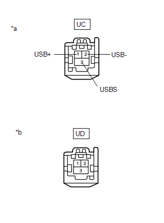
INSPECT NO. 1 NAVIGATION WIRE |
|
*a |
Front view of wire harness connector (to Navigation ECU) |
|
*b |
Front view of wire harness connector (to Instrument Panel Wire) |
(a) Disconnect the UC No. 1 navigation wire connector from the navigation ECU.
(b) Disconnect the UD No. 1 navigation wire connector from the instrument panel wire.
(c) Measure the resistance according to the value(s) in the table below.
Standard Resistance:
|
Tester Connection |
Condition |
Specified Condition |
|---|---|---|
|
UC-1 (USB+) - UD-1 |
Always |
Below 1 Ω |
|
UC-2 (USB-) - UD-2 |
Always |
Below 1 Ω |
|
UC-3 (USBS) - UD-3 |
Always |
Below 1 Ω |
|
UC-1 (USB+) or UD-1 - Body ground |
Always |
10 kΩ or higher |
|
UC-2 (USB-) or UD-2 - Body ground |
Always |
10 kΩ or higher |
|
UC-3 (USBS) or UD-3 - Body ground |
Always |
10 kΩ or higher |
| NG | |
REPAIR OR REPLACE HARNESS OR CONNECTOR |
|
|
7. |
CHECK DCM (TELEMATICS TRANSCEIVER) |
(a) Replace the DCM (telematics transceiver) with a new one.
Click here
(b) Clear the DTCs.
Body Electrical > Navigation System > Clear DTCs(c) Turn the engine switch off.
(d) Turn the engine switch on (IG) and wait for 90 seconds.
(e) Recheck for DTCs and check that no DTCs are output.
Body Electrical > Navigation System > Trouble CodesOK:
No DTCs are output.
| OK | |
END (DCM (TELEMATICS TRANSCEIVER) IS DEFECTIVE) |
|
|
8. |
CHECK NAVIGATION ECU |
(a) Replace the navigation ECU with a new one.
Click here
(b) Clear the DTCs.
Body Electrical > Navigation System > Clear DTCs(c) Turn the engine switch off.
(d) Turn the engine switch on (IG) and wait for 90 seconds.
(e) Recheck for DTCs and check that no DTCs are output.
Body Electrical > Navigation System > Trouble CodesOK:
No DTCs are output.
| OK | |
END (NAVIGATION ECU IS DEFECTIVE) |
| NG | |
REPLACE RADIO AND DISPLAY RECEIVER ASSEMBLY |
 Speaker Output Short (B15C3)
DESCRIPTION
This DTC is stored when a malfunction occurs in the speakers.
DTC No.
Detection Item
DTC Detection Condition
Trouble Area
B15 ...
 Speed Signal Malfunction (B15C2)
DESCRIPTION
The navigation ECU receives a vehicle speed signal from the combination meter
assembly and information from the navigation antenna assembly, and then adjusts
the vehicle position on t ...
Other materials:
Toyota CH-R Owners Manual > Steps to take in an emergency: If you think something is wrong
If you notice any of the following symptoms, your vehicle probably
needs adjustment or repair. Contact your Toyota dealer as soon as possible.
Visible symptoms
Fluid leaks under the vehicle.(Water dripping from the air conditioning
after use is normal.)
Flat-looking tires or uneven ti ...
Toyota CH-R Service Manual > Meter / Gauge System: Entire Combination Meter does not Operate
DESCRIPTION
This circuit is the power source circuit for the combination meter assembly.
This circuit provides two types of power sources; one is a constant power source,
and the other is an IG power source.
WIRING DIAGRAM
CAUTION / NOTICE / HINT
NOTICE:
Inspect the fuses of circu ...
Toyota C-HR (AX20) 2023-2026 Owner's Manual
Toyota CH-R Owners Manual
- For safety and security
- Instrument cluster
- Operation of each component
- Driving
- Interior features
- Maintenance and care
- When trouble arises
- Vehicle specifications
- For owners
Toyota CH-R Service Manual
- Introduction
- Maintenance
- Audio / Video
- Cellular Communication
- Navigation / Multi Info Display
- Park Assist / Monitoring
- Brake (front)
- Brake (rear)
- Brake Control / Dynamic Control Systems
- Brake System (other)
- Parking Brake
- Axle And Differential
- Drive Shaft / Propeller Shaft
- K114 Cvt
- 3zr-fae Battery / Charging
- Networking
- Power Distribution
- Power Assist Systems
- Steering Column
- Steering Gear / Linkage
- Alignment / Handling Diagnosis
- Front Suspension
- Rear Suspension
- Tire / Wheel
- Tire Pressure Monitoring
- Door / Hatch
- Exterior Panels / Trim
- Horn
- Lighting (ext)
- Mirror (ext)
- Window / Glass
- Wiper / Washer
- Door Lock
- Heating / Air Conditioning
- Interior Panels / Trim
- Lighting (int)
- Meter / Gauge / Display
- Mirror (int)
- Power Outlets (int)
- Pre-collision
- Seat
- Seat Belt
- Supplemental Restraint Systems
- Theft Deterrent / Keyless Entry

0.0092