Toyota CH-R Service Manual: Telephone And Gps Antenna Cords
Components
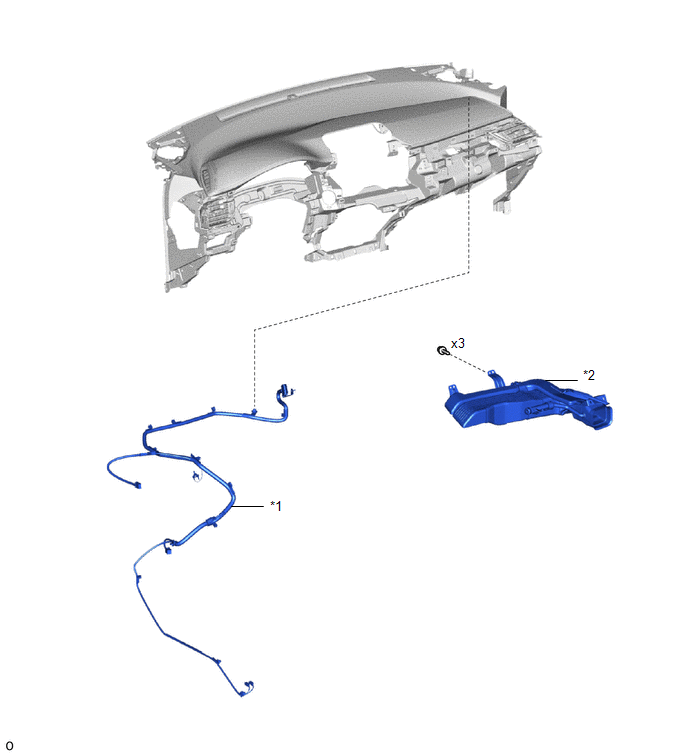
COMPONENTS
ILLUSTRATION
|
*1 |
TELEPHONE AND GPS ANTENNA CORD ASSEMBLY |
*2 |
NO. 3 HEATER TO REGISTER DUCT SUB-ASSEMBLY |
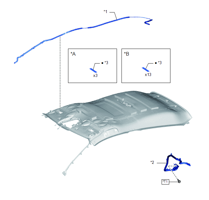
ILLUSTRATION
|
*A |
for Type A |
*B |
for Type B |
|
*1 |
NO. 2 TELEPHONE AND GPS ANTENNA CORD ASSEMBLY |
*2 |
NO. 3 TELEPHONE AND GPS ANTENNA CORD ASSEMBLY |
|
*3 |
ADHESIVE TAPE |
- |
- |
.png) |
N*m (kgf*cm, ft.*lbf): Specified torque |
● |
Non-reusable part |
|
*T1 |
for Type A: 10.5 N*m (107 kgf*cm, 8 ft.*lbf) for Type B: 10 N*m (102 kgf*cm, 7 ft.*lbf) for Type C: 10 N*m (102 kgf*cm, 7 ft.*lbf) |
- |
- |
Removal
REMOVAL
CAUTION / NOTICE / HINT
The necessary procedures (adjustment, calibration, initialization, or registration) that must be performed after parts are removed and installed, or replaced the during telephone and GPS antenna cord assembly removal/installation are shown below.
Necessary Procedures After Parts Removed/Installed/Replaced|
Replaced Part or Performed Procedure |
Necessary Procedure |
Effect/Inoperative Function when Necessary Procedure not Performed |
Link |
|---|---|---|---|
|
Disconnect cable from negative battery terminal |
Initialize back door lock |
Power door lock control system |
|
|
Memorize steering angle neutral point |
Lane departure alert system (w/ Steering Control) |
|
|
|
Pre-collision system |
CAUTION:
Some of these service operations affect the SRS airbag system. Read the precautionary notices concerning the SRS airbag system before servicing.
.png)
Click here
.gif)
PROCEDURE
1. REMOVE TELEPHONE AND GPS ANTENNA CORD ASSEMBLY
Click here
Installation
INSTALLATION
PROCEDURE
1. INSTALL TELEPHONE AND GPS ANTENNA CORD ASSEMBLY
Click here
.gif)
 Unable To Connect To Call Center
DESCRIPTION
This may occur when the intensity of telephone radio frequency was very weak,
or the safety connect system has a malfunction and a DTC is set.
PROCEDURE
1.
CHEC ...
 Telephone And Gps Antenna(for Front Side)
Components
COMPONENTS
ILLUSTRATION
*1
DEFROSTER NOZZLE ASSEMBLY
*2
TELEPHONE AND GPS ANTENNA ASSEMBLY
Removal
REMOVAL
CAUTION / NOTICE ...
Other materials:
Toyota CH-R Owners Manual > Steps to take in an emergency: If a warning message is displayed
The multi-information display shows warnings of system malfunctions,
incorrectly performed operations, and messages that indicate a need for maintenance.
When a message is shown, perform the correction procedure appropriate to the message.
Multi-information display
If any of the warning me ...
Toyota CH-R Service Manual > Airbag System: Lost communication with Side Airbag Sensor RH (B1622/81,B1623/81,B1632/81,B1633/81,B1642/81,B1643/81,B166D/81,B166E/81)
DESCRIPTION
The side collision sensor RH circuit (bus 1) consists of the airbag sensor assembly,
door side airbag sensor RH, No. 1 side airbag sensor RH and No. 2 side airbag sensor
RH.
The door side airbag sensor RH, No. 1 side airbag sensor RH and No. 2 side airbag
sensor RH detect impacts ...
Toyota C-HR (AX20) 2023-2026 Owner's Manual
Toyota CH-R Owners Manual
- For safety and security
- Instrument cluster
- Operation of each component
- Driving
- Interior features
- Maintenance and care
- When trouble arises
- Vehicle specifications
- For owners
Toyota CH-R Service Manual
- Introduction
- Maintenance
- Audio / Video
- Cellular Communication
- Navigation / Multi Info Display
- Park Assist / Monitoring
- Brake (front)
- Brake (rear)
- Brake Control / Dynamic Control Systems
- Brake System (other)
- Parking Brake
- Axle And Differential
- Drive Shaft / Propeller Shaft
- K114 Cvt
- 3zr-fae Battery / Charging
- Networking
- Power Distribution
- Power Assist Systems
- Steering Column
- Steering Gear / Linkage
- Alignment / Handling Diagnosis
- Front Suspension
- Rear Suspension
- Tire / Wheel
- Tire Pressure Monitoring
- Door / Hatch
- Exterior Panels / Trim
- Horn
- Lighting (ext)
- Mirror (ext)
- Window / Glass
- Wiper / Washer
- Door Lock
- Heating / Air Conditioning
- Interior Panels / Trim
- Lighting (int)
- Meter / Gauge / Display
- Mirror (int)
- Power Outlets (int)
- Pre-collision
- Seat
- Seat Belt
- Supplemental Restraint Systems
- Theft Deterrent / Keyless Entry

0.0078