Toyota CH-R Service Manual: Manual (SOS) Switch Red Indicator Malfunction (B1570)
DESCRIPTION
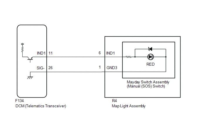
This DTC is stored when the DCM (Telematics Transceiver) detects an open or short in the manual (SOS) switch red indicator circuit of the manual (SOS) switch.
The manual (SOS) switch red indicator illuminates for 2 seconds and goes off when the ignition switch turned to ON. If a malfunction in the safety connect system is detected, the manual (SOS) switch red indicator will illuminate.
However, the manual (SOS) switch red indicator may not illuminate when this DTC is set.
|
DTC No. |
Detection Item |
DTC Detection Condition |
Trouble Area |
|---|---|---|---|
|
B1570 |
Manual (SOS) Switch Red Indicator Malfunction |
Current for manual (SOS) switch red indicator reaches malfunction criteria for 10 seconds when ignition switch is ON. |
|
WIRING DIAGRAM
CAUTION / NOTICE / HINT
HINT:
- Before performing this diagnostic procedure, make sure to perform Health
Check and confirm that the DCM/VIN registration information is correct.
Click here
.gif)
- The manual (SOS) switch red indicator may not operate to indicate another DTC has been set, therefore voice guidance is provided.
PROCEDURE
|
1. |
CHECK DTC |
(a) Turn the ignition switch off.
(b) Connect the Techstream to the DLC3.
(c) Turn the ignition switch ON and wait for 10 seconds.
(d) Turn the Techstream on.
(e) Clear the DTCs.
Body Electrical > Telematics > Clear DTCs(f) Recheck for DTCs.
Body Electrical > Telematics > Trouble Codes|
Result |
Proceed to |
|---|---|
|
DTC B1570, B1571 and B15C5 are output |
A |
|
DTC B1570 is output (DTC B1571 and B15C5 are not output) |
B |
| B | .gif) |
GO TO STEP 6 |
|
.gif)
|
2. |
INSPECT MAP LIGHT ASSEMBLY (RED INDICATOR) |
|
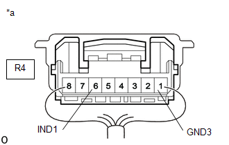
(a) Disconnect the R4 map light assembly connector. |
|
(b) Connect 2 dry-cell batteries (1.5 V each) in series.
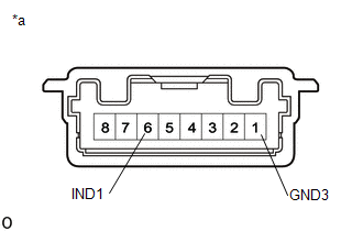
(c) Connect the positive (+) lead to terminal 6 (IND1) and the negative (-) lead to terminal 1 (GND3) of the map light assembly connector.
(d) Check if the illumination for the manual (SOS) switch red indicator comes on.
OK:
Red indicator comes on.
| NG | |
GO TO STEP 5 |
|
|
3. |
CHECK HARNESS AND CONNECTOR (DCM (TELEMATICS TRANSCEIVER) - MAP LIGHT ASSEMBLY) |
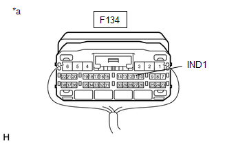
(a) Disconnect the F134 DCM (Telematics Transceiver) connector.
(b) Disconnect the R4 map light assembly connector.
(c) Measure the resistance according to the value(s) in the table below.
Standard Resistance:
|
Tester Connection |
Condition |
Specified Condition |
|---|---|---|
|
F134-26 (SIG-) - R4-1 (GND3) |
Always |
Below 1 Ω |
|
F134-26 (SIG-) or R4-1 (GND3) - Body ground |
Always |
10 kΩ or higher |
|
F134-11 (IND1) - R4-6 (IND1) |
Always |
Below 1 Ω |
|
F134-11 (IND1) or R4-6 (IND1) - Body ground |
Always |
10 kΩ or higher |
| NG | |
REPAIR OR REPLACE HARNESS OR CONNECTOR |
|
|
4. |
REPLACE DCM (TELEMATICS TRANSCEIVER) |
(a) Replace the DCM (Telematics Transceiver).
Click here
NOTICE:
- The ignition switch must be off.
- Do not swap the DCM (Telematics Transceiver) with one from another vehicle.
| NEXT | |
PERFORM DCM ACTIVATION |
|
5. |
INSPECT MAYDAY SWITCH ASSEMBLY (MANUAL (SOS) SWITCH) (RED INDICATOR) |
(a) Remove the mayday switch assembly (manual (SOS) switch).
Click here
(b) Inspect the mayday switch assembly (manual (SOS) switch).
Click here
| OK | |
REPLACE MAP LIGHT ASSEMBLY |
| NG | |
REPLACE MAYDAY SWITCH ASSEMBLY (MANUAL (SOS) SWITCH) |
|
6. |
CHECK MAYDAY SWITCH ASSEMBLY (MANUAL (SOS) SWITCH RED INDICATOR CONDITION) |
(a) Confirm the red indicator status after the ignition switch turned to ON.
Click here
|
Result |
Proceed to |
|---|---|
|
Red indicator remains off |
A |
|
Red indicator remains on |
B |
| B | |
GO TO STEP 12 |
|
|
7. |
INSPECT MAP LIGHT ASSEMBLY (RED INDICATOR INPUT VOLTAGE) |
|
(a) Remove the map light assembly but do not disconnect the connectors. Click here
|
|
(b) Connect the positive lead of a voltmeter to terminal R4-6 (IND1), and the negative lead to terminal R4-1 (GND3).
(c) Measure the voltage.
Standard:
1.0 to 8.5 V for 2 seconds after the ignition switch turned to ON.
0 V when the ignition switch is off.
| NG | |
GO TO STEP 9 |
|
|
8. |
INSPECT MAYDAY SWITCH ASSEMBLY (MANUAL (SOS) SWITCH) (RED INDICATOR) |
(a) Remove the mayday switch assembly (manual (SOS) switch).
Click here
(b) Inspect the mayday switch assembly (manual (SOS) switch).
Click here
| OK | |
REPLACE MAP LIGHT ASSEMBLY |
| NG | |
REPLACE MAYDAY SWITCH ASSEMBLY (MANUAL (SOS) SWITCH) |
|
9. |
INSPECT DCM (TELEMATICS TRANSCEIVER) (RED INDICATOR OUTPUT VOLTAGE) |
|
(a) Remove the DCM (Telematics Transceiver) but do not disconnect the connectors. Click here
|
|

(b) Connect the positive lead of a voltmeter to terminal F134-11 (IND1), and the negative lead to body ground.
(c) Measure the voltage.
Standard:
1.0 to 8.5 V for 2 seconds after the ignition switch turned to ON.
0 V when the ignition switch is off.
| OK | |
REPAIR OR REPLACE HARNESS OR CONNECTOR |
|
|
10. |
CHECK HARNESS AND CONNECTOR (DCM (TELEMATICS TRANSCEIVER) - BODY GROUND) |
|
(a) Remove the DCM (Telematics Transceiver) but do not disconnect the connectors. Click here
|
|
(b) Measure the resistance according to the value(s) in the table below.
Standard Resistance:
|
Tester Connection |
Condition |
Specified Condition |
|---|---|---|
|
F134-11 (IND1) - Body ground |
Always |
10 kΩ or higher |
| NG | |
REPAIR OR REPLACE HARNESS OR CONNECTOR |
|
|
11. |
REPLACE DCM (TELEMATICS TRANSCEIVER) |
(a) Replace the DCM (Telematics Transceiver).
Click here
NOTICE:
- The ignition switch must be off.
- Do not swap the DCM (Telematics Transceiver) with one from another vehicle.
Click here
| NEXT | |
PERFORM DCM ACTIVATION |
|
12. |
REPLACE DCM (TELEMATICS TRANSCEIVER) |
(a) Replace the DCM (Telematics Transceiver).
Click here
NOTICE:
- The ignition switch must be off.
- Do not swap the DCM (Telematics Transceiver) with one from another vehicle.
| NEXT | |
PERFORM DCM ACTIVATION |
 Short in Telephone SUB Antenna Circuit (B1536,B1537)
DESCRIPTION
These DTCs are stored when the DCM (Telematics Transceiver) detects an open or
a short in the telephone and GPS antenna assembly (for Front Side) circuit. The
DCM (Telematics Transcei ...
 Dcm Power Source Circuit
DESCRIPTION
This is the power source circuit to operate the DCM (Telematics Transceiver).
WIRING DIAGRAM
CAUTION / NOTICE / HINT
NOTICE:
Inspect the fuses for circuits related to this system be ...
Other materials:
Toyota CH-R Service Manual > Front Disc Brake Pad: Installation
INSTALLATION
CAUTION / NOTICE / HINT
NOTICE:
Immediately after installing the brake pads, the braking performance
may be reduced. Always perform a road test in a safe place while paying
attention to the surroundings.
Immediately after installing the front disc brake pads, the ...
Toyota CH-R Service Manual > Toyota Entune System: Confirm Vehicle Headunit Functionality
PROCEDURE
1.
CHECK CUSTOMER'S CELLULAR PHONE COMPATIBILITY
(a) Check if the cellular phone is compatible (Refer to http://www.toyota.com/Entune/).
Result
Proceed to
Cellular phone is compatible.
A
...
Toyota C-HR (AX20) 2023-2026 Owner's Manual
Toyota CH-R Owners Manual
- For safety and security
- Instrument cluster
- Operation of each component
- Driving
- Interior features
- Maintenance and care
- When trouble arises
- Vehicle specifications
- For owners
Toyota CH-R Service Manual
- Introduction
- Maintenance
- Audio / Video
- Cellular Communication
- Navigation / Multi Info Display
- Park Assist / Monitoring
- Brake (front)
- Brake (rear)
- Brake Control / Dynamic Control Systems
- Brake System (other)
- Parking Brake
- Axle And Differential
- Drive Shaft / Propeller Shaft
- K114 Cvt
- 3zr-fae Battery / Charging
- Networking
- Power Distribution
- Power Assist Systems
- Steering Column
- Steering Gear / Linkage
- Alignment / Handling Diagnosis
- Front Suspension
- Rear Suspension
- Tire / Wheel
- Tire Pressure Monitoring
- Door / Hatch
- Exterior Panels / Trim
- Horn
- Lighting (ext)
- Mirror (ext)
- Window / Glass
- Wiper / Washer
- Door Lock
- Heating / Air Conditioning
- Interior Panels / Trim
- Lighting (int)
- Meter / Gauge / Display
- Mirror (int)
- Power Outlets (int)
- Pre-collision
- Seat
- Seat Belt
- Supplemental Restraint Systems
- Theft Deterrent / Keyless Entry

0.0086