Toyota CH-R Service Manual: Side Turn Signal Light Bulb
Components
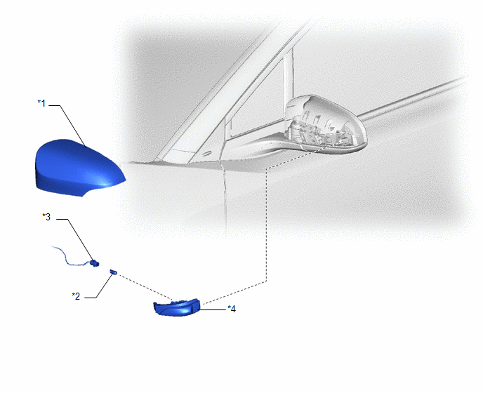
COMPONENTS
ILLUSTRATION
|
*1 |
OUTER MIRROR COVER |
*2 |
SIDE TURN SIGNAL BULB |
|
*3 |
SIDE TURN SIGNAL LIGHT SOCKET |
*4 |
SIDE TURN SIGNAL LIGHT ASSEMBLY |
Removal
REMOVAL
CAUTION / NOTICE / HINT
HINT:
- Use the same procedure for the RH and LH sides.
- The procedure listed below is for the LH side.
PROCEDURE
1. REMOVE OUTER MIRROR COVER
Click here
.gif)
2. REMOVE SIDE TURN SIGNAL BULB
(a) Disengage the claws to separate the side turn signal light assembly as shown in the illustration.
.png)
.png) |
Remove in this Direction |
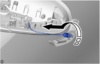
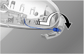
(b) Turn the side turn signal light socket with bulb as shown in the illustration to disconnect them as a unit.
|
|
Remove in this Direction |
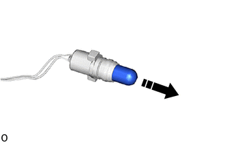
(c) Remove the side turn signal light bulb from the side turn signal light socket and wire as shown in the illustration.
|
|
Remove in this Direction |
Installation
INSTALLATION
CAUTION / NOTICE / HINT
HINT:
- Use the same procedure for the RH and LH sides.
- The procedure listed below is for the LH side.
PROCEDURE
1. INSTALL SIDE TURN SIGNAL LIGHT BULB
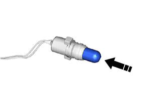
(a) Install the side turn signal light bulb to the side turn signal light socket as shown in the illustration.
.png) |
Install in this Direction |
(b) Turn the side turn signal light socket with bulb as shown in the illustration to connect them as a unit.
|
|
Install in this Direction |
(c) Engage the claws to install the side turn signal light assembly as shown in the illustration.
.png)
|
|
Install in this Direction |
2. INSTALL OUTER MIRROR COVER
Click here
.gif)
 Side Turn Signal Light Assembly
Components
COMPONENTS
ILLUSTRATION
*1
OUTER MIRROR COVER
*2
SIDE TURN SIGNAL BULB
*3
SIDE TURN SIGNAL LIGHT ASSEMBLY
...

Other materials:
Toyota CH-R Service Manual > Id Code Box: Removal
REMOVAL
CAUTION / NOTICE / HINT
The necessary procedures (adjustment, calibration, initialization, or registration)
that must be performed after parts are removed, installed, or replaced during the
ID code box (immobiliser code ECU) removal/installation are shown below.
Necessary Procedure Af ...
Toyota CH-R Service Manual > Audio And Visual System(for Radio And Display Type): Poor Sound Quality in All Modes (Low Volume)
PROCEDURE
1.
CHECK AUDIO SETTINGS
(a) Set bass, mid-range and treble to the initial values and check that the sound
is normal.
OK:
The sound returns to normal.
HINT:
Sound quality adjustment measures vary according to the type of amplifier.
OK
...
Toyota C-HR (AX20) 2023-2026 Owner's Manual
Toyota CH-R Owners Manual
- For safety and security
- Instrument cluster
- Operation of each component
- Driving
- Interior features
- Maintenance and care
- When trouble arises
- Vehicle specifications
- For owners
Toyota CH-R Service Manual
- Introduction
- Maintenance
- Audio / Video
- Cellular Communication
- Navigation / Multi Info Display
- Park Assist / Monitoring
- Brake (front)
- Brake (rear)
- Brake Control / Dynamic Control Systems
- Brake System (other)
- Parking Brake
- Axle And Differential
- Drive Shaft / Propeller Shaft
- K114 Cvt
- 3zr-fae Battery / Charging
- Networking
- Power Distribution
- Power Assist Systems
- Steering Column
- Steering Gear / Linkage
- Alignment / Handling Diagnosis
- Front Suspension
- Rear Suspension
- Tire / Wheel
- Tire Pressure Monitoring
- Door / Hatch
- Exterior Panels / Trim
- Horn
- Lighting (ext)
- Mirror (ext)
- Window / Glass
- Wiper / Washer
- Door Lock
- Heating / Air Conditioning
- Interior Panels / Trim
- Lighting (int)
- Meter / Gauge / Display
- Mirror (int)
- Power Outlets (int)
- Pre-collision
- Seat
- Seat Belt
- Supplemental Restraint Systems
- Theft Deterrent / Keyless Entry

0.0096