Toyota CH-R Owners Manual: Head restraints
Head restraints are provided for all seats.
Head restraints are provided for all seats.
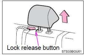
- Up
Pull the head restraints up. - Down
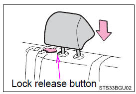
Push the head restraint down while pressing the lock release button.
Rear seats
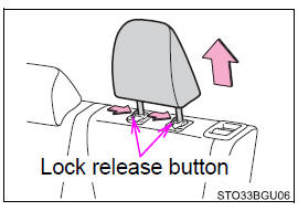
■ Rear outboard seats
- To fold
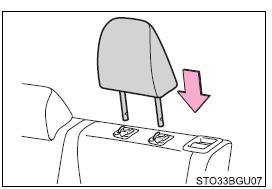
Pull the head restraint up while pressing the lock release button. - To use
Lift up and push down the head restraint to the lowest lock position.
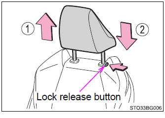
■ Rear center seat
- Up
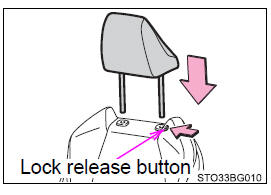
Pull the head restraints up. - Down
Push the head restraint down while pressing the lock release button.
■Removing the head restraints
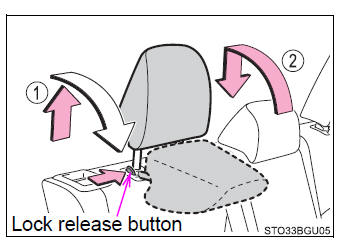
Front seats
Pull the head restraint up while pressing the lock release button.
Rear outside seats
Pull the head restraint up while pressing the both lock release buttons.
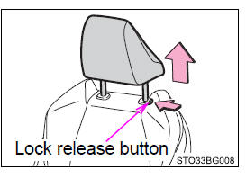
Rear center seat
Pull the head restraint up while pressing the lock release button.
■Installing the head restraints
Front seats
Align the head restraint with the installation holes and push it down to the lock position.
Press and hold the lock release button when lowering the head restraint.
Rear outside seats
Align the head restraint with the installation holes and push it down to the lock position.
Rear center seat
Align the head restraint with the installation holes and push it down to the lock position.
Press and hold the lock release button when lowering the head restraint.
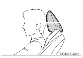
■Adjusting the height of the front seat head restraints
Make sure that the head restraints are adjusted so that the center of the head restraint is closest to the top of your ears.
■Adjusting the rear center seat head restraint
Always raise the head restraint one level from the stowed position when using.
■Head restraint precautions Observe the following precautions regarding the head restraints. Failure to do so may result in death or serious injury.
- Use the head restraints designed for each respective seat.
- Adjust the head restraints to the correct position at all times.
- After adjusting the head restraints, push down on them and make sure they are locked in position.
- Do not drive with the head restraints removed.
 Rear seats
The seatbacks of the rear seats can be folded down.
Before folding down the seatbacks
Park the vehicle in a safe place.Apply the parking brake firmly and shift
the shift lever to P.
Adju ...

Other materials:
Toyota CH-R Service Manual > Smart Key System(for Entry Function): All Door Entry Lock/Unlock Functions do not Operate, but Wireless Functions
Operate
DESCRIPTION
When the wireless operation can be used to lock and unlock the doors, communication
between the electrical key and TPMS receiver assembly and certification ECU (smart
key ECU assembly) is normal. If the entry lock and unlock functions do not operate,
the entry cancel function may ...
Toyota CH-R Service Manual > Navigation System: Start Up Signal Circuit between Radio Receiver Assembly and Navigation ECU
DESCRIPTION
This circuit includes the navigation ECU and radio and display receiver assembly.
WIRING DIAGRAM
PROCEDURE
1.
CHECK HARNESS AND CONNECTOR (RADIO AND DISPLAY RECEIVER ASSEMBLY - NAVIGATION
ECU)
(a) Disconnect the F130 radio and display receiver a ...
Toyota C-HR (AX20) 2023-2026 Owner's Manual
Toyota CH-R Owners Manual
- For safety and security
- Instrument cluster
- Operation of each component
- Driving
- Interior features
- Maintenance and care
- When trouble arises
- Vehicle specifications
- For owners
Toyota CH-R Service Manual
- Introduction
- Maintenance
- Audio / Video
- Cellular Communication
- Navigation / Multi Info Display
- Park Assist / Monitoring
- Brake (front)
- Brake (rear)
- Brake Control / Dynamic Control Systems
- Brake System (other)
- Parking Brake
- Axle And Differential
- Drive Shaft / Propeller Shaft
- K114 Cvt
- 3zr-fae Battery / Charging
- Networking
- Power Distribution
- Power Assist Systems
- Steering Column
- Steering Gear / Linkage
- Alignment / Handling Diagnosis
- Front Suspension
- Rear Suspension
- Tire / Wheel
- Tire Pressure Monitoring
- Door / Hatch
- Exterior Panels / Trim
- Horn
- Lighting (ext)
- Mirror (ext)
- Window / Glass
- Wiper / Washer
- Door Lock
- Heating / Air Conditioning
- Interior Panels / Trim
- Lighting (int)
- Meter / Gauge / Display
- Mirror (int)
- Power Outlets (int)
- Pre-collision
- Seat
- Seat Belt
- Supplemental Restraint Systems
- Theft Deterrent / Keyless Entry

0.0079