Toyota CH-R Service Manual: Steering Lock does not Lock
DESCRIPTION
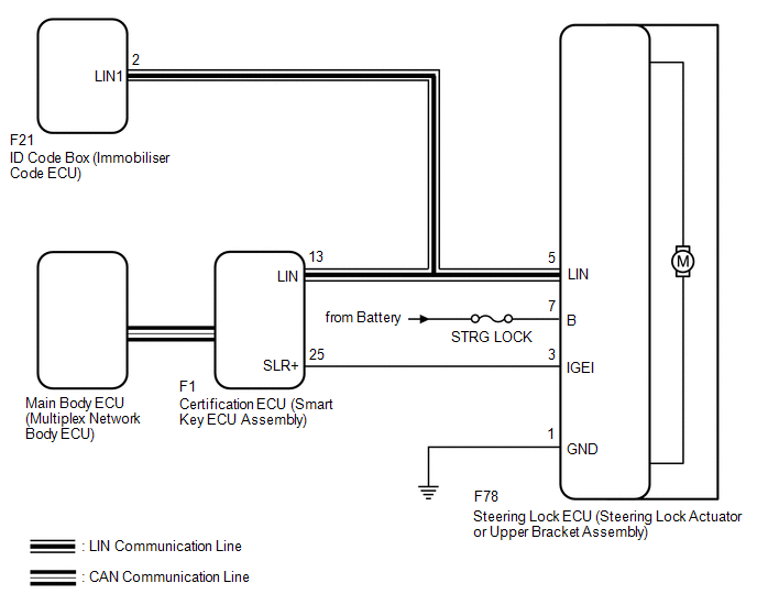
The steering lock actuator or upper bracket assembly activates the steering lock motor and moves the lock bar into the steering column to lock the steering.
When the steering lock is operating, the steering may not lock when the lock bar is not aligned with the lock hole of the steering column. In this case, the steering can be locked by turning the steering wheel a little, as is done for a vehicle with a mechanical key, to change the position of the lock hole.
Related Data List and Active Test Items|
Problem Symptom |
Data List Item |
Active Test Item |
|---|---|---|
|
Steering Lock does not Lock |
Smart Key
Main Body
Power Source Control
|
- |
WIRING DIAGRAM
CAUTION / NOTICE / HINT
NOTICE:
- When using the Techstream with the engine switch off, connect the Techstream to the vehicle and turn a courtesy light switch on and off at intervals of 1.5 seconds or less until communication between the Techstream and the vehicle begins. Then select the vehicle type under manual mode and enter the following menus: Body Electrical / Smart Key. While using the Techstream, periodically turn a courtesy light switch on and off at intervals of 1.5 seconds or less to maintain communication between the Techstream and the vehicle.
- Perform either of the following operations to lock/unlock the steering:
- To unlock the steering, carry the key and turn the engine switch on (ACC) or on (IG).
- To lock the steering, turn the engine switch off with the shift lever in P, and then open a door.
- Make sure that no DTCs are output. If any DTCs are output, proceed to
the Diagnostic Trouble Code Chart.
Click here
.gif)
- The steering lock system uses LIN communication. First perform the inspections
in "How to Proceed with Troubleshooting" to confirm that there are no communication
malfunctions before proceeding with troubleshooting.
Click here
- When replacing the steering lock ECU (steering lock actuator or upper
bracket assembly), certification ECU (smart key ECU assembly) or ID code
box (immobiliser code ECU), registration must be performed.
Click here
- After performing repairs, confirm that the problem does not recur.
- Inspect the fuses for circuits related to this system before performing the following procedure.
- When disconnecting the cable from the negative (-) battery terminal,
some systems need to be initialized after the cable is reconnected.
Click here
PROCEDURE
|
1. |
READ VALUE USING VALUE USING TECHSTREAM (LOCK REQUEST RECEIVE) |
(a) Use the Data List to check if the steering lock command is functioning properly.
Body Electrical > Smart Key > Data List|
Tester Display |
Measurement Item |
Range |
Normal Condition |
Diagnostic Note |
|---|---|---|---|---|
|
Lock Request Receive |
Reception state of steering lock request signal by certification ECU (smart key ECU assembly) sent to ID code box (immobiliser code ECU) HINT:
|
OK or NG |
OK: Lock request received within 10 seconds of opening any door with engine switch off and shift lever in P NG: Except above |
If this item does not change to "OK" even though the steering lock conditions are met, the certification ECU (smart key ECU assembly) may be malfunctioning. |
|
Tester Display |
|---|
|
Lock Request Receive |
OK:
The certification ECU (smart key ECU assembly) receives a lock request signal within 10 seconds of turning the engine switch from on (IG) to on (ACC) or off and opening a door with the shift lever in P, and OK is displayed on the Techstream screen.
| NG | .gif) |
GO TO STEP 10 |
|
.gif)
|
2. |
READ VALUE USING VALUE USING TECHSTREAM (S CODE CHECK) |
(a) Use the Data List to check if S code certification is functioning properly.
Body Electrical > Smart Key > Data List|
Tester Display |
Measurement Item |
Range |
Normal Condition |
Diagnostic Note |
|---|---|---|---|---|
|
S Code Check |
Verification result between certification ECU (smart key ECU assembly) and ID code box (immobiliser code ECU) |
OK or NG |
OK: Verification result normal NG: Verification result abnormal |
When a malfunction is present:
|
|
Tester Display |
|---|
|
S Code Check |
OK:
OK is displayed on the Techstream.
HINT:
Reasons for verification failure:
- The certification ECU (smart key ECU assembly) or ID code box (immobiliser code ECU) is malfunctioning.
- There is a problem with the communication between ECUs.
- An ECU is replaced, but is not registered.
- An ECU is replaced with an ECU which has a code already stored in it.
| NG | |
GO TO STEP 9 |
|
|
3. |
READ VALUE USING VALUE USING TECHSTREAM (L CODE CHECK) |
(a) Use the Data List to check if L code certification is functioning properly.
Body Electrical > Smart Key > Data List|
Tester Display |
Measurement Item |
Range |
Normal Condition |
Diagnostic Note |
|---|---|---|---|---|
|
L Code Check |
Verification result between ID code box (immobiliser code ECU) and steering lock ECU (steering lock actuator or upper bracket assembly) |
OK or NG |
OK: Verification result normal NG: Verification result abnormal |
When a malfunction is present:
|
|
Tester Display |
|---|
|
L Code Check |
OK:
OK is displayed on the Techstream.
HINT:
Reasons for verification failure:
- The steering lock ECU (steering lock actuator or upper bracket assembly) or ID code box (immobiliser code ECU) is malfunctioning.
- There is a problem with the communication between ECUs.
- An ECU is replaced, but is not registered.
- An ECU is replaced with an ECU which has a code already stored in it.
| NG | |
GO TO STEP 8 |
|
|
4. |
CHECK HARNESS AND CONNECTOR (POWER SOURCE TERMINAL) |
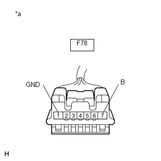
(a) Disconnect the F78 steering lock ECU (steering lock actuator or upper bracket assembly) connector.
|
(b) Measure the resistance and voltage according to the value(s) in the table below. Standard Resistance:
NOTICE: If the result is not as specified, check for looseness in the ground cable connection. Standard Voltage:
|
|
| NG | |
REPAIR OR REPLACE HARNESS OR CONNECTOR |
|
|
5. |
INSPECT STEERING LOCK ECU (STEERING LOCK ACTUATOR OR UPPER BRACKET ASSEMBLY) |
(a) Reconnect the F78 steering lock ECU (steering lock actuator or upper bracket assembly) connector.
|
(b) Check the signal waveform according to the condition(s) in the table below. Standard Frequency:
HINT:
|
|
.png)
| OK | |
REPLACE STEERING LOCK ECU (STEERING LOCK ACTUATOR OR UPPER BRACKET ASSEMBLY) |
|
|
6. |
CHECK HARNESS AND CONNECTOR (STEERING LOCK ECU (STEERING LOCK ACTUATOR OR UPPER BRACKET ASSEMBLY) - CERTIFICATION ECU (SMART KEY ECU ASSEMBLY)) |
(a) Make sure that there is no looseness at the locking part and the connecting part of the connectors.
(b) Disconnect the F78 steering lock ECU (steering lock actuator or upper bracket assembly) connector.
(c) Disconnect the F1 certification ECU (smart key ECU assembly) connector.
(d) Check for deformation and corrosion of the connector case and terminals.
OK:
There is no deformation or corrosion of the connector case or terminals.
(e) Measure the resistance according to the value(s) in the table below.
Standard Resistance:
|
Tester Connection |
Condition |
Specified Condition |
|---|---|---|
|
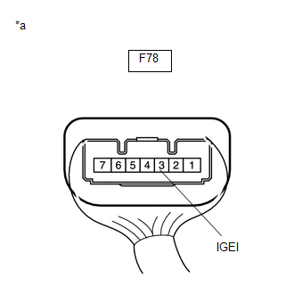
F78-3 (IGEI) - F1-25 (SLR+) |
Always |
Below 1 Ω |
|
F78-3 (IGEI) or F1-25 (SLR+) - Body ground |
Always |
10 kΩ or higher |
| NG | |
REPAIR OR REPLACE HARNESS OR CONNECTOR |
|
|
7. |
INSPECT STEERING LOCK ECU (STEERING LOCK ACTUATOR OR UPPER BRACKET ASSEMBLY) |
(a) Reconnect the F78 steering lock ECU (steering lock actuator or upper bracket assembly) connector.
(b) Reconnect the F1 certification ECU (smart key ECU assembly) connector.
|
(c) Measure the voltage according to the value(s) in the table below. Standard Voltage:
|
|
| OK | |
REPLACE CERTIFICATION ECU (SMART KEY ECU ASSEMBLY) |
| NG | |
REPLACE STEERING LOCK ECU (STEERING LOCK ACTUATOR OR UPPER BRACKET ASSEMBLY) |
|
8. |
REPLACE STEERING LOCK ECU (STEERING LOCK ACTUATOR OR UPPER BRACKET ASSEMBLY) |
(a) Replace the steering lock ECU (steering lock actuator or upper bracket assembly) with a new one.
Click here
(b) Perform registration.
Click here
(c) Use the Data List to check if L code certification is functioning properly.
Body Electrical > Smart Key > Data List|
Tester Display |
Measurement Item |
Range |
Normal Condition |
Diagnostic Note |
|---|---|---|---|---|
|
L Code Check |
Verification result between ID code box (immobiliser code ECU) and steering lock ECU (steering lock actuator or upper bracket assembly) |
OK or NG |
OK: Verification result normal NG: Verification result abnormal |
When a malfunction is present:
|
|
Tester Display |
|---|
|
L Code Check |
OK:
OK is displayed on the Techstream.
| OK | |
END |
| NG | |
REPLACE ID CODE BOX (IMMOBILISER CODE ECU) |
|
9. |
REPLACE CERTIFICATION ECU (SMART KEY ECU ASSEMBLY) |
(a) Replace the certification ECU (smart key ECU assembly) with a new one.
(b) Perform registration.
Click here
(c) Use the Data List to check if S code certification is functioning properly.
Body Electrical > Smart Key > Data List|
Tester Display |
Measurement Item |
Range |
Normal Condition |
Diagnostic Note |
|---|---|---|---|---|
|
S Code Check |
Verification result between certification ECU (smart key ECU assembly) and ID code box (immobiliser code ECU) |
OK or NG |
OK: Verification result normal NG: Verification result abnormal |
When a malfunction is present:
|
|
Tester Display |
|---|
|
S Code Check |
OK:
OK is displayed on the Techstream.
| OK | |
END |
| NG | |
REPLACE ID CODE BOX (IMMOBILISER CODE ECU) |
|
10. |
READ VALUE USING VALUE USING TECHSTREAM (DOOR COURTESY SW) |
(a) Using the Techstream, check the following main body ECU (multiplex network body ECU) Data List item by opening and closing the driver door to confirm the state of the front door courtesy light switch assembly.
Body Electrical > Main Body > Data List|
Tester Display |
Measurement Item |
Range |
Normal Condition |
Diagnostic Note |
|---|---|---|---|---|
|
FL Door Courtesy SW |
Front door courtesy light switch assembly LH |
ON or OFF |
ON: Front door LH open OFF: Front door LH closed |
If this item does not change according to the actual state of the driver door, there is a malfunction in the door courtesy light switch or related part. |
|
Tester Display |
|---|
|
FL Door Courtesy SW |
OK:
The Data List item changes in accordance with the opening and closing of the driver door.
| NG | |
GO TO LIGHTING SYSTEM (DOOR COURTESY SWITCH CIRCUIT) |
|
|
11. |
READ VALUE USING VALUE USING TECHSTREAM (SHIFT P SIGNAL) |
(a) Move the shift lever to P.
(b) Read the Data List according to the display on the Techstream.
Body Electrical > Power Source Control > Data List|
Tester Display |
Measurement Item |
Range |
Normal Condition |
Diagnostic Note |
|---|---|---|---|---|
|
Shift P Signal |
Shift position (P) signal |
ON or OFF |
ON: Shift lever in P OFF: Shift lever not in P |
|
|
Tester Display |
|---|
|
Shift P Signal |
OK:
ON is displayed on the Techstream.
| NG | |
GO TO SMART KEY SYSTEM (for Start Function) (PROBLEM SYMPTOMS TABLE)
|
|
|
12. |
READ VALUE USING VALUE USING TECHSTREAM (STEERING LOCK) |
(a) Check that the steering is unlocked.
(b) Read the Data List according to the display on the Techstream.
Body Electrical > Smart Key > Data List|
Tester Display |
Measurement Item |
Range |
Normal Condition |
Diagnostic Note |
|---|---|---|---|---|
|
Steering Lock |
State of whether steering lock ECU (steering lock actuator or upper bracket assembly) determined steering is locked |
Set or Unset |
Set: Steering locked Unset: Steering unlocked |
If this item displays "Unset", the steering is not locked. |
|
Tester Display |
|---|
|
Steering Lock |
OK:
Set is displayed on the Techstream.
| NG | |
REPLACE STEERING LOCK ECU (STEERING LOCK ACTUATOR OR UPPER BRACKET ASSEMBLY) |
|
|
13. |
READ VALUE USING VALUE USING TECHSTREAM (LOCK REQUEST RECEIVE) |
(a) Replace the certification ECU (smart key ECU assembly) with a new one.
(b) Perform registration.
Click here
(c) Turn the engine switch on (IG).
(d) Use the Data List to check if the steering lock command is functioning properly.
Body Electrical > Smart Key > Data List|
Tester Display |
Measurement Item |
Range |
Normal Condition |
Diagnostic Note |
|---|---|---|---|---|
|
Lock Request Receive |
Reception state of steering lock request signal by certification ECU (smart key ECU assembly) sent to ID code box (immobiliser code ECU) HINT:
|
OK or NG |
OK: Lock request received within 10 seconds of opening any door with engine switch off and shift lever in P NG: Except above |
If this item does not change to "OK" even though the steering lock conditions are met, the certification ECU (smart key ECU assembly) may be malfunctioning. |
|
Tester Display |
|---|
|
Lock Request Receive |
OK:
The certification ECU (smart key ECU assembly) receives a lock request signal within 10 seconds of turning the engine switch from on (IG) to on (ACC) or off and opening a door with the shift lever in P, and OK is displayed on the Techstream screen.
| OK | |
END |
| NG | |
REPLACE ID CODE BOX (IMMOBILISER CODE ECU) |
 Power Source Control ECU Malfunction (B2782)
DESCRIPTION
The certification ECU (smart key ECU assembly) has a power source mode switching
function.
This DTC is stored when the IGEI input (the steering lock motor activation permission
signa ...
 Unable to Unlock Steering Wheel (Engine cannot Start)
DESCRIPTION
The steering lock actuator or upper bracket assembly activates the steering lock
motor and moves the lock bar into the steering column to lock the steering.
The steering may not unlock ...
Other materials:
Toyota CH-R Service Manual > Smart Key System(for Start Function): Parts Location
PARTS LOCATION
ILLUSTRATION
*1
PARK/NEUTRAL POSITION SWITCH
*2
STARTER ASSEMBLY
*3
NO. 1 ENGINE ROOM RELAY BLOCK
- IG2-MAIN FUSE
- ECU-IG2 NO. 1 FUSE
- ST FUSE
- WIPER FUSE
- ST RELAY
*4
...
Toyota CH-R Owners Manual > Dynamic radar cruise control with full-speed range: Selecting constant speed control mode
When constant speed control mode is selected, your vehicle will maintain a set
speed without controlling the vehicle-to-vehicle distance.
Select this mode only when vehicle-to-vehicle distance control mode does not
function correctly due to a dirty radar sensor, etc.
1. With the cruise control ...
Toyota C-HR (AX20) 2023-2026 Owner's Manual
Toyota CH-R Owners Manual
- For safety and security
- Instrument cluster
- Operation of each component
- Driving
- Interior features
- Maintenance and care
- When trouble arises
- Vehicle specifications
- For owners
Toyota CH-R Service Manual
- Introduction
- Maintenance
- Audio / Video
- Cellular Communication
- Navigation / Multi Info Display
- Park Assist / Monitoring
- Brake (front)
- Brake (rear)
- Brake Control / Dynamic Control Systems
- Brake System (other)
- Parking Brake
- Axle And Differential
- Drive Shaft / Propeller Shaft
- K114 Cvt
- 3zr-fae Battery / Charging
- Networking
- Power Distribution
- Power Assist Systems
- Steering Column
- Steering Gear / Linkage
- Alignment / Handling Diagnosis
- Front Suspension
- Rear Suspension
- Tire / Wheel
- Tire Pressure Monitoring
- Door / Hatch
- Exterior Panels / Trim
- Horn
- Lighting (ext)
- Mirror (ext)
- Window / Glass
- Wiper / Washer
- Door Lock
- Heating / Air Conditioning
- Interior Panels / Trim
- Lighting (int)
- Meter / Gauge / Display
- Mirror (int)
- Power Outlets (int)
- Pre-collision
- Seat
- Seat Belt
- Supplemental Restraint Systems
- Theft Deterrent / Keyless Entry

0.0074