Toyota CH-R Service Manual: Manual(sos)switch
Components
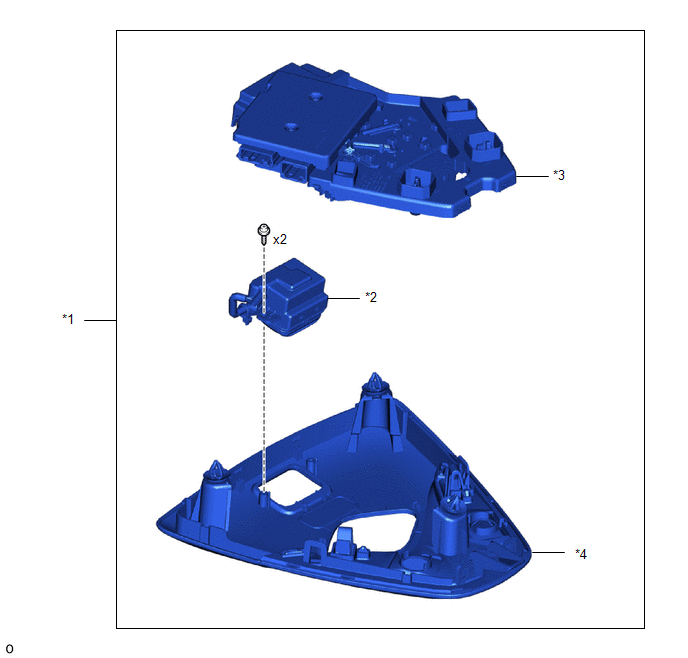
COMPONENTS
ILLUSTRATION
|
*1 |
MAP LIGHT ASSEMBLY |
*2 |
MANUAL (SOS) SWITCH (MAYDAY SWITCH ASSEMBLY) |
|
*3 |
COVER |
*4 |
BEZEL |
Removal
REMOVAL
PROCEDURE
1. REMOVE MAP LIGHT ASSEMBLY
Click here
.gif)
2. REMOVE MANUAL (SOS) SWITCH (MAYDAY SWITCH ASSEMBLY)
|
(a) Disconnect the connector. |
|
|
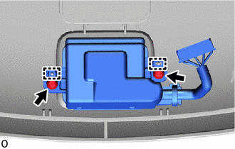
(b) Disengage the claws to remove the cover. |
|
|
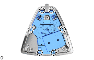
(c) Using a T10 "TORX" driver, remove the 2 screws. |
|
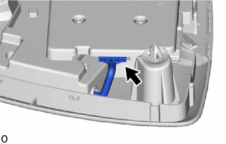
(d) Disengage the guides to remove the manual (SOS) switch (mayday switch assembly) from the bezel.
Inspection
INSPECTION
PROCEDURE
1. INSPECT MANUAL (SOS) SWITCH (MAYDAY SWITCH ASSEMBLY)
|
(a) Check the resistance. (1) Measure the resistance according to the value(s) in the table below. Standard Resistance:
If the resistance is not as specified, replace the manual (SOS) switch (mayday switch assembly). |
|
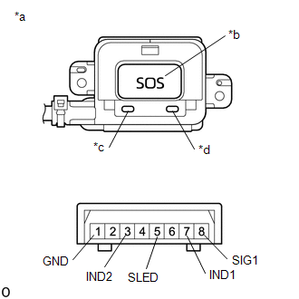
(b) Check the switch illumination.
(1) Apply battery voltage to the manual (SOS) switch (mayday switch assembly) and check that the illumination comes on.
OK:
|
Battery Connection |
Specified Condition |
|---|---|
|
Battery positive (+) → 5 (SLED) Battery negative (-) → 1 (GND) |
SOS switch comes on |
If the resistance is not as specified, replace the manual (SOS) switch (mayday switch assembly).
(c) Check the indicator illumination.
(1) Apply battery voltage to the manual (SOS) switch (mayday switch assembly) and check that the illumination comes on.
OK:
|
Battery Connection |
Specified Condition |
|---|---|
|
Battery positive (+) → 7 (IND1) Battery negative (-) → 1 (GND) |
Red indicator comes on |
|
Battery positive (+) → 3 (IND2) Battery negative (-) → 1 (GND) |
Green indicator comes on |
If the resistance is not as specified, replace the manual (SOS) switch (mayday switch assembly).
Installation
INSTALLATION
PROCEDURE
1. INSTALL MANUAL (SOS) SWITCH (MAYDAY SWITCH ASSEMBLY)
|
(a) Engage the guides to install the manual (SOS) switch (mayday switch assembly) to the bezel. |
|
.png)
(b) Using a T10 "TORX" driver, install the 2 screws.
|
(c) Engage the claws to install the cover. |
|
.png)
(d) Connect the connector.
2. INSTALL MAP LIGHT ASSEMBLY
Click here
.gif)
 Dcm(telematics Transceiver)
Components
COMPONENTS
ILLUSTRATION
*1
DCM (TELEMATICS TRANSCEIVER)
-
-
N*m (kgf*cm, ft.*lbf): Specified torque
- ...

Other materials:
Toyota CH-R Service Manual > Immobiliser System(w/o Smart Key System): Diagnosis System
DIAGNOSIS SYSTEM
DESCRIPTION
(a) The transponder key ECU assembly controls the immobiliser system. Immobiliser
system data and Diagnostic Trouble Codes (DTCs) can be read through the vehicle
Data Link Connector 3 (DLC3).
CHECK DLC3
(a) Check the DLC3.
Click here
INSPECT BATTERY VOLTAGE
...
Toyota CH-R Service Manual > Immobiliser System(w/ Smart Key System): Theft Deterrent System Communication Line High Fixation (B279A)
DESCRIPTION
If the communication line (IMI - EFIO) between the ECM and ID code box (immobiliser
code ECU) is stuck high, the ECM will store this DTC.
DTC No.
Detection Item
DTC Detection Condition
Trouble Area
Note
B279A
...
Toyota C-HR (AX20) 2023-2026 Owner's Manual
Toyota CH-R Owners Manual
- For safety and security
- Instrument cluster
- Operation of each component
- Driving
- Interior features
- Maintenance and care
- When trouble arises
- Vehicle specifications
- For owners
Toyota CH-R Service Manual
- Introduction
- Maintenance
- Audio / Video
- Cellular Communication
- Navigation / Multi Info Display
- Park Assist / Monitoring
- Brake (front)
- Brake (rear)
- Brake Control / Dynamic Control Systems
- Brake System (other)
- Parking Brake
- Axle And Differential
- Drive Shaft / Propeller Shaft
- K114 Cvt
- 3zr-fae Battery / Charging
- Networking
- Power Distribution
- Power Assist Systems
- Steering Column
- Steering Gear / Linkage
- Alignment / Handling Diagnosis
- Front Suspension
- Rear Suspension
- Tire / Wheel
- Tire Pressure Monitoring
- Door / Hatch
- Exterior Panels / Trim
- Horn
- Lighting (ext)
- Mirror (ext)
- Window / Glass
- Wiper / Washer
- Door Lock
- Heating / Air Conditioning
- Interior Panels / Trim
- Lighting (int)
- Meter / Gauge / Display
- Mirror (int)
- Power Outlets (int)
- Pre-collision
- Seat
- Seat Belt
- Supplemental Restraint Systems
- Theft Deterrent / Keyless Entry

0.0089