
Toyota CH-R Service Manual: Dcm(telematics Transceiver)
Components
COMPONENTS
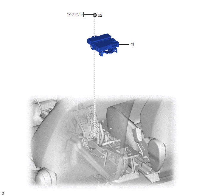
ILLUSTRATION
|
*1 |
DCM (TELEMATICS TRANSCEIVER) |
- |
- |
.png) |
N*m (kgf*cm, ft.*lbf): Specified torque |
- |
- |
Removal
REMOVAL
CAUTION / NOTICE / HINT
The necessary procedures (adjustment, calibration, initialization, or registration) that must be performed after parts are removed and installed, or replaced during DCM (telematics transceiver) removal/installation are shown below.
Necessary Procedures After Parts Removed/Installed/Replaced|
Replacement Part or Procedure |
Necessary Procedure |
Effect/Inoperative when not Performed |
Link |
|---|---|---|---|
|
Replacement of DCM (telematics transceiver) |
DCM activation |
Safety connect system |
|
PROCEDURE
1. REMOVE REAR CONSOLE BOX ASSEMBLY
Click here
.gif)
2. REMOVE DCM (TELEMATICS TRANSCEIVER)
|
(a) Disconnect the 5 connectors. |
|
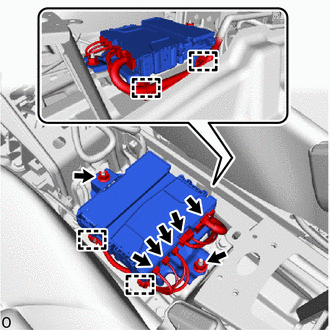
(b) Disengage the clamps.
(c) Remove the 2 nuts and DCM (telematics transceiver).
Installation
INSTALLATION
PROCEDURE
1. INSTALL DCM (TELEMATICS TRANSCEIVER)
|
(a) Install the DCM (telematics transceiver) with the 2 nuts. Torque: 12 N·m {122 kgf·cm, 9 ft·lbf} |
|
.png)
(b) Engage the clamps.
(c) Connect the 5 connectors.
2. INSTALL REAR CONSOLE BOX ASSEMBLY
Click here
.gif)
3. PERFORM REGISTRATION
HINT:
When replacing the DCM (telematics transceiver), perform DCM activation.
Click here
 Back-up Battery
Components
COMPONENTS
ILLUSTRATION
*1
MOBILEPHONE BATTERY
*2
TRANSCEIVER COVER
Removal
REMOVAL
CAUTION / NOTICE / HINT
The necessary p ...
 Manual(sos)switch
Components
COMPONENTS
ILLUSTRATION
*1
MAP LIGHT ASSEMBLY
*2
MANUAL (SOS) SWITCH (MAYDAY SWITCH ASSEMBLY)
*3
COVER
...
Other materials:
Toyota CH-R Service Manual > Lin Communication System: Terminals Of Ecu
TERMINALS OF ECU
CHECK INSTRUMENT PANEL JUNCTION BLOCK ASSEMBLY AND MAIN BODY ECU (MULTIPLEX NETWORK
BODY ECU)
*A
1 Connector Type
-
-
*A
2 Connector Type
-
-
(a) Disconnect the MB mai ...
Toyota CH-R Service Manual > Can Communication System: Front Camera Module Communication Stop Mode
DESCRIPTION
Detection Item
Symptom
Trouble Area
Front Camera Module Communication Stop Mode
Any of the following conditions are met:
Communication stop for "Front Camera Module" is indicated on
the "Comm ...
Toyota C-HR (AX20) 2023-2026 Owner's Manual
Toyota CH-R Owners Manual
- For safety and security
- Instrument cluster
- Operation of each component
- Driving
- Interior features
- Maintenance and care
- When trouble arises
- Vehicle specifications
- For owners
Toyota CH-R Service Manual
- Introduction
- Maintenance
- Audio / Video
- Cellular Communication
- Navigation / Multi Info Display
- Park Assist / Monitoring
- Brake (front)
- Brake (rear)
- Brake Control / Dynamic Control Systems
- Brake System (other)
- Parking Brake
- Axle And Differential
- Drive Shaft / Propeller Shaft
- K114 Cvt
- 3zr-fae Battery / Charging
- Networking
- Power Distribution
- Power Assist Systems
- Steering Column
- Steering Gear / Linkage
- Alignment / Handling Diagnosis
- Front Suspension
- Rear Suspension
- Tire / Wheel
- Tire Pressure Monitoring
- Door / Hatch
- Exterior Panels / Trim
- Horn
- Lighting (ext)
- Mirror (ext)
- Window / Glass
- Wiper / Washer
- Door Lock
- Heating / Air Conditioning
- Interior Panels / Trim
- Lighting (int)
- Meter / Gauge / Display
- Mirror (int)
- Power Outlets (int)
- Pre-collision
- Seat
- Seat Belt
- Supplemental Restraint Systems
- Theft Deterrent / Keyless Entry

0.009