Toyota CH-R Service Manual: Back-up Battery
Components
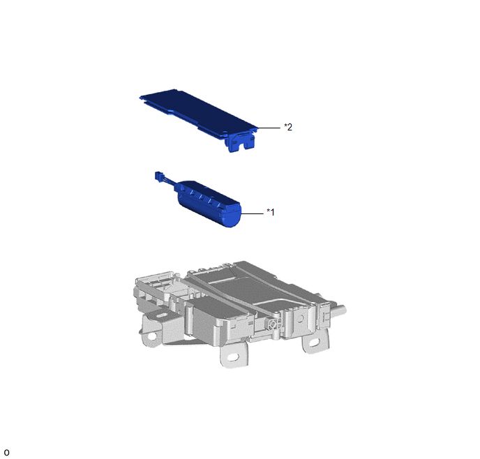
COMPONENTS
ILLUSTRATION
|
*1 |
MOBILEPHONE BATTERY |
*2 |
TRANSCEIVER COVER |
Removal
REMOVAL
CAUTION / NOTICE / HINT
The necessary procedures (adjustment, calibration, initialization, or registration) that must be performed after parts are removed, installed, or replaced during the mayday battery removal/installation are shown below.
Necessary Procedures After Parts Removed/Installed/Replaced|
Replacement Part or Procedure |
Necessary Procedure |
Effect/Inoperative when not Performed |
Link |
|---|---|---|---|
|
Mobilephone battery |
Reset mobilephone battery condition |
Safety connect system |
|
PROCEDURE
1. REMOVE DCM (TELEMATICS TRANSCEIVER)
Click here
.gif)
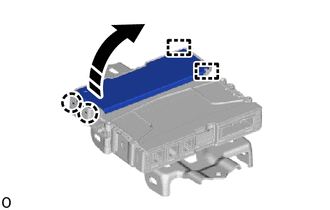
2. REMOVE TRANSCEIVER COVER
(a) Disengage the claws and guides to remove the transceiver cover as shown in the illustration.
.png) |
Remove in this Direction |
3. REMOVE MOBILEPHONE BATTERY
|
(a) Disconnect the connector. |
|
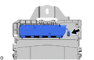
(b) Remove the mobilephone battery.
Installation
INSTALLATION
PROCEDURE
1. INSTALL MOBILEPHONE BATTERY
(a) Install the mobilephone battery.
(b) Connect the connector.
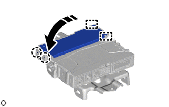
2. INSTALL TRANSCEIVER COVER
(a) Engage the guides and claws to install the transceiver cover as shown in the illustration.
.png) |
Install in this Direction |
3. INSTALL DCM (TELEMATICS TRANSCEIVER)
Click here
.gif)
4. PERFORM REGISTRATION
Click here

 Dcm(telematics Transceiver)
Components
COMPONENTS
ILLUSTRATION
*1
DCM (TELEMATICS TRANSCEIVER)
-
-
N*m (kgf*cm, ft.*lbf): Specified torque
- ...
Other materials:
Toyota CH-R Service Manual > Smart Key System(for Start Function): Diagnosis System
DIAGNOSIS SYSTEM
DESCRIPTION
(a) Smart key system (for Start Function) data and Diagnostic Trouble Codes (DTCs)
can be read through the Data Link Connector 3 (DLC3) of the vehicle. When the system
seems to be malfunctioning, use the Techstream to check for malfunctions and perform
repairs.
...
Toyota CH-R Service Manual > Vehicle Stability Control System: Stop Light Control Relay Malfunction (C1380)
DESCRIPTION
When the dynamic radar cruise control system*1, pre-collision system*1 or brake
hold control system operates, the skid control ECU outputs a stop light drive output
(STPO) signal to illuminate the stop lights.
*1: w/ Pre-collision System
DTC No.
Detection Ite ...
Toyota C-HR (AX20) 2023-2026 Owner's Manual
Toyota CH-R Owners Manual
- For safety and security
- Instrument cluster
- Operation of each component
- Driving
- Interior features
- Maintenance and care
- When trouble arises
- Vehicle specifications
- For owners
Toyota CH-R Service Manual
- Introduction
- Maintenance
- Audio / Video
- Cellular Communication
- Navigation / Multi Info Display
- Park Assist / Monitoring
- Brake (front)
- Brake (rear)
- Brake Control / Dynamic Control Systems
- Brake System (other)
- Parking Brake
- Axle And Differential
- Drive Shaft / Propeller Shaft
- K114 Cvt
- 3zr-fae Battery / Charging
- Networking
- Power Distribution
- Power Assist Systems
- Steering Column
- Steering Gear / Linkage
- Alignment / Handling Diagnosis
- Front Suspension
- Rear Suspension
- Tire / Wheel
- Tire Pressure Monitoring
- Door / Hatch
- Exterior Panels / Trim
- Horn
- Lighting (ext)
- Mirror (ext)
- Window / Glass
- Wiper / Washer
- Door Lock
- Heating / Air Conditioning
- Interior Panels / Trim
- Lighting (int)
- Meter / Gauge / Display
- Mirror (int)
- Power Outlets (int)
- Pre-collision
- Seat
- Seat Belt
- Supplemental Restraint Systems
- Theft Deterrent / Keyless Entry

0.0084