Toyota CH-R Service Manual: Terminals Of Ecu
TERMINALS OF ECU
CHECK MAIN BODY ECU (MULTIPLEX NETWORK BODY ECU) AND INSTRUMENT PANEL JUNCTION BLOCK ASSEMBLY (w/ Retract Mirror)
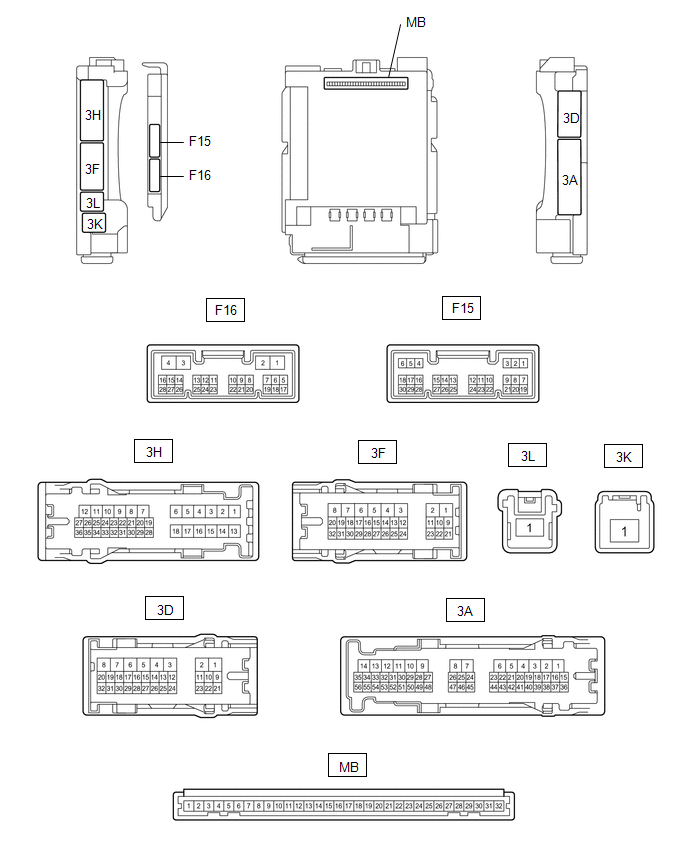
(a) Remove the main body ECU (multiplex network body ECU) from the instrument panel junction block assembly.
Click here
.gif)
(b) Reconnect the instrument panel junction block assembly connectors.
(c) Measure the resistance and voltage according to the value(s) in the table below.
HINT:
Measure the values on the wire harness side with the connector disconnected.
|
Terminal No. (Symbol) |
Wiring Color |
Terminal Description |
Condition |
Specified Condition |
|---|---|---|---|---|
|
MB-11 (GND1) - Body ground |
- |
Ground |
Always |
Below 1 Ω |
|
MB-31 (BECU) - Body ground |
- |
Battery power supply |
Always |
11 to 14 V |
|
MB-30 (ACC) - Body ground |
- |
Ignition power supply (ACC signal) |
Ignition switch ACC |
11 to 14 V |
|
MB-30 (ACC) - Body ground |
- |
Ignition power supply (ACC signal) |
Ignition switch off |
Below 1 V |
|
MB-32 (IG) - Body ground |
- |
Ignition power supply (IG signal) |
Ignition switch ON |
11 to 14 V |
|
MB-32 (IG) - Body ground |
- |
Ignition power supply (IG signal) |
Ignition switch off |
Below 1 V |
(d) Install the main body ECU (multiplex network body ECU) to instrument panel junction block assembly.
Click here
(e) Measure the voltage according to the value(s) in the table below.
|
Terminal No. (Symbol) |
Wiring Color |
Terminal Description |
Condition |
Specified Condition |
|---|---|---|---|---|
|
F16-14 (RET) - Body ground |
B - Body ground |
Power retract mirror motor drive voltage |
Mirror retract switch on outer mirror switch assembly retracted position. |
Below 1 V |
|
Mirror retract switch on outer mirror switch assembly driving position. |
11 to 14 V |
|||
|
F16-15 (RTR) - Body ground |
P - Body ground |
Power retract mirror motor drive voltage |
Mirror retract switch on outer mirror switch assembly auto retracted position. |
Below 1 V |
|
Mirror retract switch on outer mirror switch assembly driving position. |
11 to 14 V |
|||
|
F16-19 (RETR) - Body ground |
L - Body ground |
Power retract mirror motor drive voltage |
Outer rear view mirror assembly moves to the retracted position. |
Below 1 V |
|
Outer rear view mirror assembly not move. |
11 to 14 V |
|||
|
F16-20 (RTRR) - Body ground |
R - Body ground |
Power retract mirror motor drive voltage |
Outer rear view mirror assembly moves to the driving position. |
Below 1 V |
|
Outer rear view mirror assembly not move. |
11 to 14 V |
CHECK AIR CONDITIONING AMPLIFIER ASSEMBLY
Click here
CHECK AIR CONDITIONING CONTROL ASSEMBLY
Click here
 Problem Symptoms Table
PROBLEM SYMPTOMS TABLE
NOTICE:
If the battery voltage is low, the mirror heater function may not operate. In
this case, check the Data List item "Battery Control Count (Body ECU)".
Clic ...
 Diagnosis System
DIAGNOSIS SYSTEM
CHECK DLC3
(a) Check the DLC3.
Click here
INSPECT BATTERY VOLTAGE
(a) Measure the battery voltage with the ignition switch off.
Standard Voltage:
11 to 14 V
If the voltag ...
Other materials:
Toyota CH-R Service Manual > Blind Spot Monitor System: Blind Spot Monitor Slave Module (C1AB7)
DESCRIPTION
This DTC is stored when the blind spot monitor sensor RH (Slave) detects an internal
malfunction.
DTC No.
Detection Item
DTC Detection Condition
Trouble Area
C1AB7
Blind Spot Monitor Slave Module
The b ...
Toyota CH-R Service Manual > Cellular Communication: Telephone And Gps Antenna(for Front Side)
Components
COMPONENTS
ILLUSTRATION
*1
DEFROSTER NOZZLE ASSEMBLY
*2
TELEPHONE AND GPS ANTENNA ASSEMBLY
Removal
REMOVAL
CAUTION / NOTICE / HINT
The necessary procedures (adjustment, calibration, initialization, or registration)
that m ...
Toyota C-HR (AX20) 2023-2026 Owner's Manual
Toyota CH-R Owners Manual
- For safety and security
- Instrument cluster
- Operation of each component
- Driving
- Interior features
- Maintenance and care
- When trouble arises
- Vehicle specifications
- For owners
Toyota CH-R Service Manual
- Introduction
- Maintenance
- Audio / Video
- Cellular Communication
- Navigation / Multi Info Display
- Park Assist / Monitoring
- Brake (front)
- Brake (rear)
- Brake Control / Dynamic Control Systems
- Brake System (other)
- Parking Brake
- Axle And Differential
- Drive Shaft / Propeller Shaft
- K114 Cvt
- 3zr-fae Battery / Charging
- Networking
- Power Distribution
- Power Assist Systems
- Steering Column
- Steering Gear / Linkage
- Alignment / Handling Diagnosis
- Front Suspension
- Rear Suspension
- Tire / Wheel
- Tire Pressure Monitoring
- Door / Hatch
- Exterior Panels / Trim
- Horn
- Lighting (ext)
- Mirror (ext)
- Window / Glass
- Wiper / Washer
- Door Lock
- Heating / Air Conditioning
- Interior Panels / Trim
- Lighting (int)
- Meter / Gauge / Display
- Mirror (int)
- Power Outlets (int)
- Pre-collision
- Seat
- Seat Belt
- Supplemental Restraint Systems
- Theft Deterrent / Keyless Entry

0.0072