Toyota CH-R Service Manual: Ambient Temperature Display System
DESCRIPTION
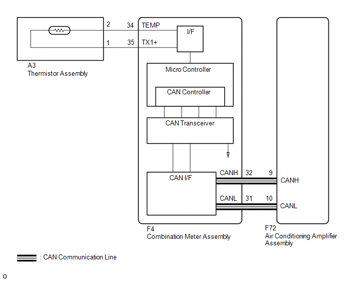
The outside temperature sensor is installed in front of the cooler condenser assembly to detect the ambient temperature which is used to control the air conditioning system AUTO mode. This sensor is connected to the combination meter assembly and detects fluctuations in the ambient temperature. This data is used for controlling the cabin temperature. The sensor sends a signal to the air conditioning amplifier assembly from the combination meter assembly via CAN communication.
The resistance of the outside temperature sensor changes in accordance with the ambient temperature. As the temperature increases, the resistance decreases. Conversely, as the temperature decreases, the resistance increases. The combination meter assembly applies a voltage (5 V) to the outside temperature sensor and reads voltage changes due to changes in the resistance of the outside temperature sensor.
NOTICE:
The thermistor assembly is installed on the front of the cooler condenser assembly in the engine room and detects the ambient temperature around the installation area (the ambient temperature detected is the temperature detected around the thermistor assembly and not the ambient temperature of the air surrounding the vehicle). Therefore, the ambient temperature around the thermistor assembly changes depending on the radiated heat from the engine room and the ambient temperature display value is affected by vehicle speed. In the following cases, the ambient temperature of the air surrounding the vehicle and the displayed value are different and the speed at which the displayed value updates is delayed. However, this is not a malfunction.
- When the vehicle is stopped or being driven at a low speed, the value is not updated to a higher temperature in order to minimize the effects of the radiated heat from the engine on the heater and air conditioner "AUTO" control. Since the same adjustment also occurs while the vehicle is being driven at medium to high speeds, updating to a higher temperature is delayed. However, the value is updated to a lower temperature regardless of the vehicle speed.
- The ambient temperature around the thermistor assembly installation area drastically changes due to a cause other than the radiated heat from the engine (vehicle garage, entering or exiting a tunnel, etc.).
WIRING DIAGRAM
CAUTION / NOTICE / HINT
NOTICE:
- After turning the ignition switch off, waiting time may be required
before disconnecting the cable from the negative (-) battery terminal. Therefore,
make sure to read the disconnecting the cable from the negative (-) battery
terminal notices before proceeding with work.
Click here
.gif)
- Before starting the inspection, it is necessary to release the residual
heat from the engine room (engine unit and coolant hoses, etc.) after stopping
the engine (when the vehicle is parked after being driven). Therefore, move
and park the vehicle in the following type of temperature measurement location.
- A location within the vehicle service area which has a relatively low amount of environmental temperature changes in the area surrounding the vehicle.
- A location with a level surface made of a material such as concrete which transmits a relatively low amount of heat from the ground, such as concrete.
- A location with no heat influences around the vehicle to be inspected such as other vehicles with a running engine and electric motors, exhaust gas ducts installed on the exhaust pipes, stoves, etc.
- The air conditioning system uses the CAN communication system. Inspect
the communication function by following How to Proceed with Troubleshooting.
Troubleshoot the air conditioning system after confirming that the communication
system is functioning properly.
Click here
- Ignition switch operation during parked vehicle inspection:
Turn the ignition switch ON. (Do not start the engine.)
PROCEDURE
|
1. |
CHECK FOR DTC |
(a) Clear the DTC.
Click here
(b) Check for DTCs when the following conditions are met.
Click here
NOTICE:
During the parked vehicle inspection, perform the inspection with the ignition switch ON (do not start the engine).
|
Result |
Proceed to |
|---|---|
|
DTC B1412 is not output |
A |
|
DTC B1412 is output |
B |
| B | .gif) |
GO TO DTC B1412 |
|
.gif)
|
2. |
INSPECT THERMISTOR ASSEMBLY |
(a) Remove the thermistor assembly.
Click here
(b) Inspect the thermistor assembly.
Click here
| NG | |
REPLACE THERMISTOR ASSEMBLY |
|
|
3. |
CHECK HARNESS AND CONNECTOR (THERMISTOR ASSEMBLY - COMBINATION METER ASSEMBLY) |
NOTICE:
During the parked vehicle inspection, perform the inspection with the ignition switch off (do not start the engine).
(a) Disconnect the A3 thermistor assembly connector.
(b) Disconnect the F4 combination meter assembly connector.
(c) Measure the resistance according to the value(s) in the table below.
Standard Resistance:
|
Tester Connection |
Condition |
Specified Condition |
|---|---|---|
|
A3-2 - F4-34 (TEMP) |
Always |
Below 1 Ω |
|
A3-1 - F4-35 (TX1+) |
Always |
Below 1 Ω |
|
A3-1 - A3-2 |
Always |
10 kΩ or higher |
|
A3-2 or F4-34 (TEMP) - Body ground |
Always |
10 kΩ or higher |
|
A3-1 or F4-35 (TX1+) - Body ground |
Always |
10 kΩ or higher |
| NG | |
REPAIR OR REPLACE HARNESS OR CONNECTOR |
|
|
4. |
CHECK AMBIENT TEMPERATURE COMPARISON |
(a) Disconnect the cable from the negative (-) battery terminal.
NOTICE:
Make sure the wire harness(es) and connector(s) for the vehicle being inspected are connected. After the ignition switch is turned off, the navigation system stores the various memory and settings within approximately 6 minutes. Therefore, make sure to disconnect the cable from the negative (-) battery terminal after confirming that 6 minutes or more have elapsed since turning the ignition switch off.
(b) Disconnect the cable from the negative (-) battery terminal and wait 90 seconds or more.
HINT:
The air conditioning amplifier assembly reads and memorizes the thermistor assembly detection value from before the ignition switch was turned off for 1 hour after turning the ignition switch off. Therefore, it is necessary to switch off the air conditioning amplifier assembly internal power source and clear the stored values from before the ignition switch was turned off.
(c) Connect the cable to the negative (-) battery terminal.
(d) Using a thermometer, measure the ambient temperature of the installation area around the thermistor assembly and record it.
NOTICE:
- During the parked vehicle inspection, perform the inspection with the ignition switch ON (do not start the engine).
- Set the thermometer so that the measuring tip is at approximately the same height and lateral position as the thermistor assembly installed behind the front grille and approximately 5 cm from the surface of the front grille, and then maintain the thermometer in that position.
- After the ignition switch is turned ON, the ambient temperature, detected signal value and sensing portion temperature of the thermistor assembly and the measuring tip of the thermometer will equalize. Therefore, make sure to wait approximately 6 minutes before measuring.
- If the temperature sensing portion of the thermistor assembly is touched, the body temperature of the technician may cause an incorrect temperature measurement. Therefore, do not touch the temperature sensor when measuring the ambient temperature of the installation area around the thermistor assembly.
- Do not move the thermometer from the maintained position, touch the measuring tip or allow it to contact the front grille.
(e) Record the ambient temperature value displayed on the multi-information display of the combination meter assembly.
(f) Compare the ambient temperature of the installation area around the thermistor assembly with the ambient temperature value displayed on the multi-information display of the combination meter assembly.
Standard:
The ambient temperature of the installation area around the thermistor assembly is approximately the same as the ambient temperature value displayed on the multi-information display of the combination meter assembly.
| OK | |
END |
| NG | |
REPLACE AIR CONDITIONING AMPLIFIER ASSEMBLY |
 PTC Heater Circuit
DESCRIPTION
The air conditioning amplifier assembly sends operation signals to the PTC heater
relays when quick heater assembly operation conditions are met. Based on the signals
from the air con ...
 Back-up Power Source Circuit
DESCRIPTION
The back-up power source circuit for the air conditioning amplifier assembly
is shown below. Power is supplied even when the ignition switch is off. This power
is used for diagnostic ...
Other materials:
Toyota CH-R Service Manual > Terms: Glossary Of Sae And Toyota Terms
GLOSSARY OF SAE AND TOYOTA TERMS
This glossary lists all SAE-J1930 terms and abbreviations used in this manual
in compliance with SAE recommendations, as well as their TOYOTA equivalents.
SAE
Abbreviation
SAE Term
TOYOTA Term
( )-Abbreviation
...
Toyota CH-R Service Manual > Theft Deterrent / Keyless Entry: Electrical Key Oscillator(for Outside Luggage Compartment)
Components
COMPONENTS
ILLUSTRATION
*1
ELECTRICAL KEY ANTENNA
-
-
N*m (kgf*cm, ft.*lbf): Specified torque
-
-
Installation
INSTALLATION
PROCEDURE
1. INSTALL ELECTRICAL KEY ANTENNA
(a) En ...
Toyota C-HR (AX20) 2023-2026 Owner's Manual
Toyota CH-R Owners Manual
- For safety and security
- Instrument cluster
- Operation of each component
- Driving
- Interior features
- Maintenance and care
- When trouble arises
- Vehicle specifications
- For owners
Toyota CH-R Service Manual
- Introduction
- Maintenance
- Audio / Video
- Cellular Communication
- Navigation / Multi Info Display
- Park Assist / Monitoring
- Brake (front)
- Brake (rear)
- Brake Control / Dynamic Control Systems
- Brake System (other)
- Parking Brake
- Axle And Differential
- Drive Shaft / Propeller Shaft
- K114 Cvt
- 3zr-fae Battery / Charging
- Networking
- Power Distribution
- Power Assist Systems
- Steering Column
- Steering Gear / Linkage
- Alignment / Handling Diagnosis
- Front Suspension
- Rear Suspension
- Tire / Wheel
- Tire Pressure Monitoring
- Door / Hatch
- Exterior Panels / Trim
- Horn
- Lighting (ext)
- Mirror (ext)
- Window / Glass
- Wiper / Washer
- Door Lock
- Heating / Air Conditioning
- Interior Panels / Trim
- Lighting (int)
- Meter / Gauge / Display
- Mirror (int)
- Power Outlets (int)
- Pre-collision
- Seat
- Seat Belt
- Supplemental Restraint Systems
- Theft Deterrent / Keyless Entry

0.01