Toyota CH-R Service Manual: PTC Heater Circuit
DESCRIPTION
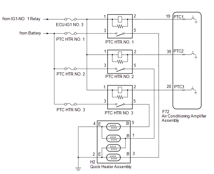
The air conditioning amplifier assembly sends operation signals to the PTC heater relays when quick heater assembly operation conditions are met. Based on the signals from the air conditioning amplifier assembly, the PTC heater relays turn on, and power is supplied to the quick heater assembly installed in the air conditioning radiator assembly.
Quick Heater Assembly Operation Condition|
Control ECU |
Condition |
|---|---|
|
Air Conditioning Amplifier Assembly |
Ignition switch ON |
|
ECO mode: off |
|
|
Blower switch: On |
|
|
Temperature setting: MAX HOT |
|
|
Light control switch off |
|
|
|
|
WIRING DIAGRAM
CAUTION / NOTICE / HINT
NOTICE:
Inspect the fuses for circuits related to this system before performing the following procedure.
PROCEDURE
|
1. |
PERFORM ACTIVE TEST USING TECHSTREAM (HEATER ACTIVE LEVEL) |
(a) Connect the Techstream to the DLC3.
(b) Turn the ignition switch ON.
(c) Turn the Techstream on.
(d) Enter the following menus: Body Electrical / Air Conditioner / Active Test.
(e) Perform the Active Test according to the display on the Techstream.
Body Electrical > Air Conditioner > Active Test|
Tester Display |
Measurement Item |
Control Range |
Diagnostic Note |
|---|---|---|---|
|
Heater Active Level |
Quick heater assembly |
Min.: 0 Max.: 3 |
- |
|
Tester Display |
|---|
|
Heater Active Level |
OK:
Heater Active Level changes normally.
| OK | .gif) |
PROCEED TO NEXT SUSPECTED AREA SHOWN IN PROBLEM SYMPTOMS TABLE |
|
.gif)
|
2. |
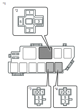
INSPECT PTC HEATER RELAY |
(a) Remove the PTC heater relays.
(b) Inspect the PTC heater relays.
Click here
.gif)
| NG | |
REPLACE PTC HEATER RELAY |
|
|
3. |
CHECK HARNESS AND CONNECTOR (PTC HEATER RELAY - POWER SOURCE) |
|
(a) Measure the voltage according to the value(s) in the table below. Standard Voltage: PTC HTR NO. 1
Standard Voltage: PTC HTR NO. 2
Standard Voltage: PTC HTR NO. 3
|
|
| NG | |
REPAIR OR REPLACE HARNESS OR CONNECTOR |
|
|
4. |
CHECK HARNESS AND CONNECTOR (PTC HEATER RELAY - AIR CONDITIONING AMPLIFIER ASSEMBLY) |
(a) Disconnect the F72 air conditioning amplifier assembly connectors.
(b) Measure the resistance according to the value(s) in the table below.
Standard Resistance:
PTC HTR NO. 1
|
Tester Connection |
Condition |
Specified Condition |
|---|---|---|
|
Relay terminal 2 - F72-19 (PTC1) |
Always |
Below 1 Ω |
|
Relay terminal 2 or F72-19 (PTC1) - Body ground |
Always |
10 kΩ or higher |
Standard Resistance:
PTC HTR NO. 2
|
Tester Connection |
Condition |
Specified Condition |
|---|---|---|
|
Relay terminal 2 - F72-39 (PTC2) |
Always |
Below 1 Ω |
|
Relay terminal 2 or F72-39 (PTC2) - Body ground |
Always |
10 kΩ or higher |
Standard Resistance:
PTC HTR NO. 3
|
Tester Connection |
Condition |
Specified Condition |
|---|---|---|
|
Relay terminal 2 -F72-20 (PTC3) |
Always |
Below 1 Ω |
|
Relay terminal 2 or F72-20 (PTC3) - Body ground |
Always |
10 kΩ or higher |
| NG | |
REPAIR OR REPLACE HARNESS OR CONNECTOR |
|
|
5. |
CHECK HARNESS AND CONNECTOR (PTC HEATER RELAY - QUICK HEATER ASSEMBLY AND BODY GROUND) |
(a) Disconnect the H2 quick heater assembly connectors.
(b) Measure the resistance according to the value(s) in the table below.
Standard Resistance:
PTC HTR NO. 1
|
Tester Connection |
Condition |
Specified Condition |
|---|---|---|
|
Relay terminal 5 - H2-3 (B) |
Always |
Below 1 Ω |
|
H2-2 (E) - Body ground |
Always |
Below 1 Ω |
|
H2-4 (E) - Body ground |
Always |
Below 1 Ω |
|
Relay terminal 5 or H2-3 (B) - Body ground |
Always |
10 kΩ or higher |
Standard Resistance:
PTC HTR NO. 2
|
Tester Connection |
Condition |
Specified Condition |
|---|---|---|
|
Relay terminal 5 - H2-1 (B) |
Always |
Below 1 Ω |
|
H2-2 (E) - Body ground |
Always |
Below 1 Ω |
|
Relay terminal 5 or H2-1 (B) - Body ground |
Always |
10 kΩ or higher |
Standard Resistance:
PTC HTR NO. 3
|
Tester Connection |
Condition |
Specified Condition |
|---|---|---|
|
Relay terminal 5 - H2-5 (B) |
Always |
Below 1 Ω |
|
H2-4 (E) - Body ground |
Always |
Below 1 Ω |
|
Relay terminal 5 or H2-5 (B) - Body ground |
Always |
10 kΩ or higher |
| NG | |
REPAIR OR REPLACE HARNESS OR CONNECTOR |
|
|
6. |
INSPECT QUICK HEATER ASSEMBLY |
(a) Remove the quick heater assembly.
Click here
(b) Inspect the quick heater assembly.
Click here
| OK | |
REPLACE AIR CONDITIONING AMPLIFIER ASSEMBLY |
| NG | |
REPLACE QUICK HEATER ASSEMBLY |
 Blower Motor Circuit
DESCRIPTION
The blower motor with fan sub-assembly is operated by signals from the air conditioning
amplifier assembly through the blower resistor. Blower motor speed signals are transmitted
in a ...
 Ambient Temperature Display System
DESCRIPTION
The outside temperature sensor is installed in front of the cooler condenser
assembly to detect the ambient temperature which is used to control the air conditioning
system AUTO mode. ...
Other materials:
Toyota CH-R Service Manual > Power Window Control System: Dtc Check / Clear
DTC CHECK / CLEAR
CHECK DTC
(a) Connect the Techstream to the DLC3.
(b) Turn the ignition switch to ON.
(c) Turn the Techstream on.
(d) Enter the following menus: Body Electrical / (desired system) / Trouble Codes.
Body Electrical > Master Switch > Trouble Codes Body Electrical > D-Do ...
Toyota CH-R Service Manual > Console Box Light: Components
COMPONENTS
ILLUSTRATION
*1
COWL SIDE TRIM BOARD LH
*2
FRONT DOOR SCUFF PLATE LH
*3
INSTRUMENT CLUSTER FINISH PANEL GARNISH ASSEMBLY
*4
INSTRUMENT PANEL BOX ASSEMBLY
*5
INSTRU ...
Toyota C-HR (AX20) 2023-2026 Owner's Manual
Toyota CH-R Owners Manual
- For safety and security
- Instrument cluster
- Operation of each component
- Driving
- Interior features
- Maintenance and care
- When trouble arises
- Vehicle specifications
- For owners
Toyota CH-R Service Manual
- Introduction
- Maintenance
- Audio / Video
- Cellular Communication
- Navigation / Multi Info Display
- Park Assist / Monitoring
- Brake (front)
- Brake (rear)
- Brake Control / Dynamic Control Systems
- Brake System (other)
- Parking Brake
- Axle And Differential
- Drive Shaft / Propeller Shaft
- K114 Cvt
- 3zr-fae Battery / Charging
- Networking
- Power Distribution
- Power Assist Systems
- Steering Column
- Steering Gear / Linkage
- Alignment / Handling Diagnosis
- Front Suspension
- Rear Suspension
- Tire / Wheel
- Tire Pressure Monitoring
- Door / Hatch
- Exterior Panels / Trim
- Horn
- Lighting (ext)
- Mirror (ext)
- Window / Glass
- Wiper / Washer
- Door Lock
- Heating / Air Conditioning
- Interior Panels / Trim
- Lighting (int)
- Meter / Gauge / Display
- Mirror (int)
- Power Outlets (int)
- Pre-collision
- Seat
- Seat Belt
- Supplemental Restraint Systems
- Theft Deterrent / Keyless Entry

0.0092