Toyota CH-R Service Manual: Blower Motor Circuit
DESCRIPTION
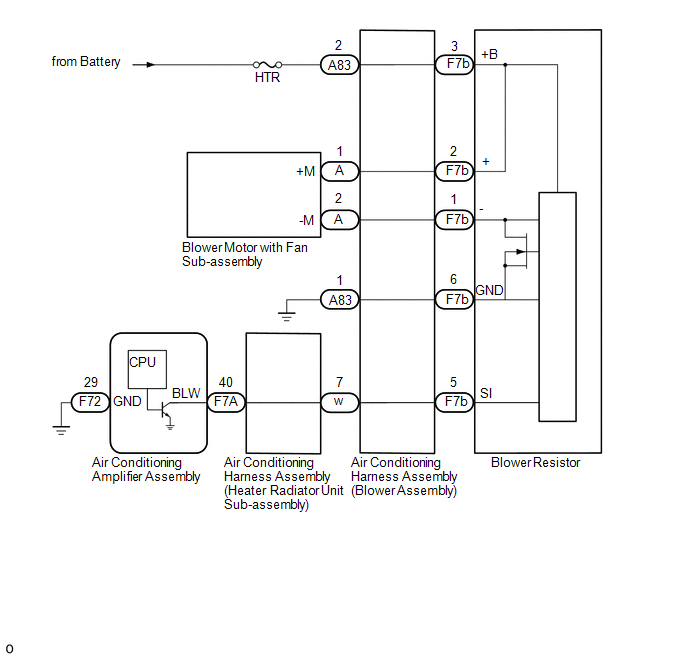
The blower motor with fan sub-assembly is operated by signals from the air conditioning amplifier assembly through the blower resistor. Blower motor speed signals are transmitted in accordance with changes in the duty ratio. The blower motor speed becomes slower when the duty interval is wider, and the blower motor speed becomes faster when the duty interval is narrower.
WIRING DIAGRAM
CAUTION / NOTICE / HINT
NOTICE:
Inspect the fuses for circuits related to this system before performing the following procedure.
PROCEDURE
|
1. |
PERFORM ACTIVE TEST USING TECHSTREAM (BLOWER MOTOR) |
(a) Connect the Techstream to the DLC3.
(b) Turn the ignition switch ON.
(c) Turn the Techstream on.
(d) Enter the following menus: Body Electrical / Air Conditioner / Active Test.
(e) Perform the Active Test according to the display on the Techstream.
Body Electrical > Air Conditioner > Active Test|
Tester Display |
Measurement Item |
Control Range |
Diagnostic Note |
|---|---|---|---|
|
Blower Motor |
Blower motor with fan sub-assembly |
Min.: 0 Max.: 100 |
Operates between 0 to 100 % |
|
Tester Display |
|---|
|
Blower Motor |
|
Result |
Proceed to |
|---|---|
|
OK |
A |
|
NG (Blower motor with fan sub-assembly does not operate) |
B |
|
NG (Blower motor with fan sub-assembly operates but does not change speed) |
C |
| A | .gif) |
PROCEED TO NEXT SUSPECTED AREA SHOWN IN PROBLEM SYMPTOMS TABLE |
| C | |
GO TO STEP 6 |
|
.gif)
|
2. |
CHECK HARNESS AND CONNECTOR (AIR CONDITIONING HARNESS ASSEMBLY (BLOWER ASSEMBLY) - POWER SOURCE) |
|
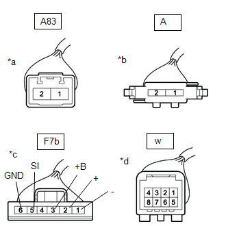
(a) Disconnect the air conditioning harness assembly (blower assembly) connector. |
|
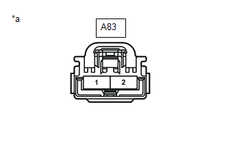
(b) Measure the voltage according to the value(s) in the table below.
Standard Voltage:
|
Tester Connection |
Condition |
Specified Condition |
|---|---|---|
|
A83-1 - A83-2 |
Always |
11 to 14 V |
(c) Measure the resistance according to the value(s) in the table below.
Standard Resistance:
|
Tester Connection |
Condition |
Specified Condition |
|---|---|---|
|
A83-1 - Body ground |
Always |
Below 1 Ω |
| NG | |
REPAIR OR REPLACE HARNESS OR CONNECTOR |
|
|
3. |
INSPECT AIR CONDITIONING HARNESS ASSEMBLY (BLOWER ASSEMBLY) |
(a) Remove the air conditioning harness assembly (blower assembly).
Click here
.gif)
|
(b) Measure the resistance according to the value(s) in the table below. Standard Resistance:
|
|
| NG | |
REPLACE AIR CONDITIONING HARNESS ASSEMBLY (BLOWER ASSEMBLY) |
|
|
4. |
INSPECT AIR CONDITIONING HARNESS ASSEMBLY (HEATER RADIATOR UNIT SUB-ASSEMBLY) |
(a) Remove the air conditioning harness assembly (heater radiator unit sub-assembly).
Click here
|
(b) Measure the resistance according to the value(s) in the table below. Standard Resistance:
|
|
| NG | |
REPLACE AIR CONDITIONING HARNESS ASSEMBLY (HEATER RADIATOR UNIT SUB-ASSEMBLY) |
|
|
5. |
INSPECT BLOWER RESISTOR |
(a) Reconnect the F7b blower resistor connector.
(b) Reconnect the w air conditioning harness assembly (blower assembly) connector.
|
(c) Measure the voltage according to the value(s) in the table below. Standard Voltage:
|
|
| NG | |
REPLACE BLOWER RESISTOR |
|
|
6. |
INSPECT AIR CONDITIONING AMPLIFIER ASSEMBLY |
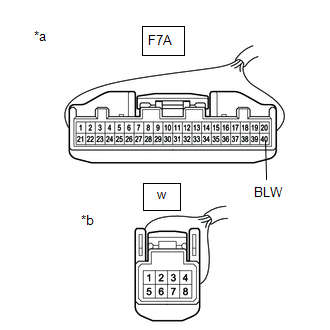
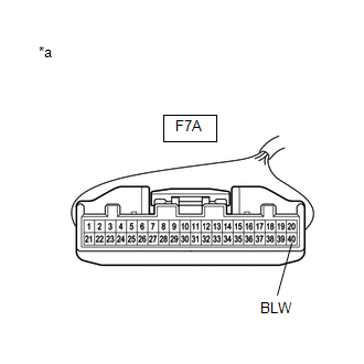
(a) Reconnect the F72 and F7A air conditioning amplifier assembly connectors.
(b) Turn the ignition switch ON.
(c) Turn the blower switch Lo.
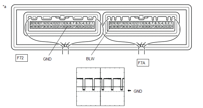
(d) Connect an oscilloscope to terminals F72-29 (GND) and F7A-40 (BLW) of the air conditioning amplifier assembly and check the waveform.
OK:
Waveform is similar to that shown in the illustration.
HINT:
The waveform varies with the blower speed.
|
Item |
Content |
|---|---|
|
Tool Setting |
2 V/DIV., 1 ms./DIV. |
|
Vehicle Condition |
|
|
*a |
Component with harness connected (Air Conditioning Amplifier Assembly) |
- |
- |
| NG | |
REPLACE AIR CONDITIONING AMPLIFIER ASSEMBLY |
|
|
7. |
REPLACE BLOWER RESISTOR |
(a) Replace the blower resistor with a new or known good one.
Click here
|
|
8. |
PERFORM ACTIVE TEST USING TECHSTREAM (BLOWER MOTOR) |
(a) Connect the Techstream to the DLC3.
(b) Turn the ignition switch ON.
(c) Turn the Techstream on.
(d) Enter the following menus: Body Electrical / Air Conditioner / Active Test.
(e) Perform the Active Test according to the display on the Techstream.
Body Electrical > Air Conditioner > Active Test|
Tester Display |
Measurement Item |
Control Range |
Diagnostic Note |
|---|---|---|---|
|
Blower Motor |
Blower motor with fan sub-assembly |
Min.: 0 Max.: 100 |
Operates between 0 to 100 % |
|
Tester Display |
|---|
|
Blower Motor |
| OK | |
END (BLOWER RESISTOR WAS DEFECTIVE) |
| NG | |
REPLACE BLOWER ASSEMBLY (BLOWER MOTOR WITH FAN SUB-ASSEMBLY) |
 Ambient Temperature Sensor Circuit (B1412)
DESCRIPTION
The thermistor assembly is installed in front of the cooler condenser assembly
to detect the ambient temperature, which is used to control the air conditioning
system. This sensor is ...
 PTC Heater Circuit
DESCRIPTION
The air conditioning amplifier assembly sends operation signals to the PTC heater
relays when quick heater assembly operation conditions are met. Based on the signals
from the air con ...
Other materials:
Toyota CH-R Service Manual > Lumbar Switch: Components
COMPONENTS
ILLUSTRATION
*1
FRONT SEAT CUSHION SHIELD
*2
RECLINING ADJUSTER RELEASE HANDLE
*3
RECLINING HINGE OUTER COVER
*4
SEAT ADJUSTER COVER CAP
*5
VERTICAL ADJUSTING HAND ...
Toyota CH-R Service Manual > Charging System: Problem Symptoms Table
PROBLEM SYMPTOMS TABLE
HINT:
Use the table below to help determine the cause of problem symptoms.
If multiple suspected areas are listed, the potential causes of the symptoms
are listed in order of probability in the "Suspected Area" column of the
table. Check each sy ...
Toyota C-HR (AX20) 2023-2026 Owner's Manual
Toyota CH-R Owners Manual
- For safety and security
- Instrument cluster
- Operation of each component
- Driving
- Interior features
- Maintenance and care
- When trouble arises
- Vehicle specifications
- For owners
Toyota CH-R Service Manual
- Introduction
- Maintenance
- Audio / Video
- Cellular Communication
- Navigation / Multi Info Display
- Park Assist / Monitoring
- Brake (front)
- Brake (rear)
- Brake Control / Dynamic Control Systems
- Brake System (other)
- Parking Brake
- Axle And Differential
- Drive Shaft / Propeller Shaft
- K114 Cvt
- 3zr-fae Battery / Charging
- Networking
- Power Distribution
- Power Assist Systems
- Steering Column
- Steering Gear / Linkage
- Alignment / Handling Diagnosis
- Front Suspension
- Rear Suspension
- Tire / Wheel
- Tire Pressure Monitoring
- Door / Hatch
- Exterior Panels / Trim
- Horn
- Lighting (ext)
- Mirror (ext)
- Window / Glass
- Wiper / Washer
- Door Lock
- Heating / Air Conditioning
- Interior Panels / Trim
- Lighting (int)
- Meter / Gauge / Display
- Mirror (int)
- Power Outlets (int)
- Pre-collision
- Seat
- Seat Belt
- Supplemental Restraint Systems
- Theft Deterrent / Keyless Entry

0.0095