Toyota CH-R Service Manual: Back-up Power Source Circuit
DESCRIPTION
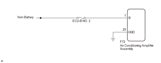
The back-up power source circuit for the air conditioning amplifier assembly is shown below. Power is supplied even when the ignition switch is off. This power is used for diagnostic trouble code memory, etc.
WIRING DIAGRAM
CAUTION / NOTICE / HINT
NOTICE:
Inspect the fuses for circuits related to this system before performing the following procedure.
PROCEDURE
|
1. |
CHECK HARNESS AND CONNECTOR (AIR CONDITIONING AMPLIFIER ASSEMBLY - POWER SOURCE) |
|
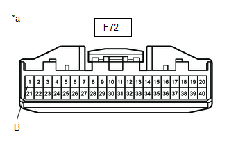
(a) Disconnect the air conditioning amplifier assembly connector. |
|
(b) Measure the voltage according to the value(s) in the table below.
Standard Voltage:
|
Tester Connection |
Condition |
Specified Condition |
|---|---|---|
|
F72-1 (B) - Body ground |
Always |
11 to 14 V |
| NG | .gif) |
REPAIR OR REPLACE HARNESS OR CONNECTOR |
|
.gif)
|
2. |
CHECK HARNESS AND CONNECTOR (AIR CONDITIONING AMPLIFIER ASSEMBLY - BODY GROUND) |
(a) Disconnect the F72 air conditioning amplifier assembly connector.
(b) Measure the resistance according to the value(s) in the table below.
Standard Resistance:
|
Tester Connection |
Condition |
Specified Condition |
|---|---|---|
|
F72-29 (GND) - Body ground |
Always |
Below 1 Ω |
| OK | |
PROCEED TO NEXT SUSPECTED AREA SHOWN IN PROBLEM SYMPTOMS TABLE |
| NG | |
REPAIR OR REPLACE HARNESS OR CONNECTOR |
 Ambient Temperature Display System
DESCRIPTION
The outside temperature sensor is installed in front of the cooler condenser
assembly to detect the ambient temperature which is used to control the air conditioning
system AUTO mode. ...
 IG Power Source Circuit
DESCRIPTION
Power source voltage is supplied to the air conditioning amplifier assembly when
the ignition switch is turned ON. This power is used for operating the air conditioning
amplifier asse ...
Other materials:
Toyota CH-R Service Manual > Front Door Courtesy Switch: Inspection
INSPECTION
PROCEDURE
1. INSPECT FRONT DOOR COURTESY LIGHT SWITCH ASSEMBLY
(a) Check the resistance.
(1) Measure the resistance according to the value(s) in the table below.
Standard Resistance:
Tester Connection
Condition
Spe ...
Toyota CH-R Service Manual > Safety Connect System: Telephone Microphone Error (B1572)
DESCRIPTION
This DTC is set when the DCM (Telematics Transceiver) detects a malfunction in
the telephone microphone assembly circuit.
DTC No.
Detection Item
DTC Detection Condition
Trouble Area
B1572
Telephone Microphone Err ...
Toyota C-HR (AX20) 2023-2026 Owner's Manual
Toyota CH-R Owners Manual
- For safety and security
- Instrument cluster
- Operation of each component
- Driving
- Interior features
- Maintenance and care
- When trouble arises
- Vehicle specifications
- For owners
Toyota CH-R Service Manual
- Introduction
- Maintenance
- Audio / Video
- Cellular Communication
- Navigation / Multi Info Display
- Park Assist / Monitoring
- Brake (front)
- Brake (rear)
- Brake Control / Dynamic Control Systems
- Brake System (other)
- Parking Brake
- Axle And Differential
- Drive Shaft / Propeller Shaft
- K114 Cvt
- 3zr-fae Battery / Charging
- Networking
- Power Distribution
- Power Assist Systems
- Steering Column
- Steering Gear / Linkage
- Alignment / Handling Diagnosis
- Front Suspension
- Rear Suspension
- Tire / Wheel
- Tire Pressure Monitoring
- Door / Hatch
- Exterior Panels / Trim
- Horn
- Lighting (ext)
- Mirror (ext)
- Window / Glass
- Wiper / Washer
- Door Lock
- Heating / Air Conditioning
- Interior Panels / Trim
- Lighting (int)
- Meter / Gauge / Display
- Mirror (int)
- Power Outlets (int)
- Pre-collision
- Seat
- Seat Belt
- Supplemental Restraint Systems
- Theft Deterrent / Keyless Entry

0.0073