Toyota CH-R Service Manual: Inspection
INSPECTION
PROCEDURE
1. INSPECT AUTOMATIC LIGHT CONTROL SENSOR
(a) Check the wire harness.
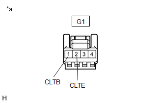
(1) Disconnect the automatic light control sensor (G1).
|
(2) Measure the voltage according to the value(s) in the table below. Standard Voltage:
If the specified condition is not met, replace the vehicle wire harness. |
|
(b) Check the resistance.
(1) Measure the resistance according to the value(s) in the table below.
Standard Resistance:
|
Tester Connection |
Switch Condition |
Specified Condition |
|---|---|---|
|
G1-2(CLTE) - Body ground |
Always |
Below 1 Ω |
If the specified condition is not met, replace the vehicle wire harness.
(c) Check the automatic light control sensor.
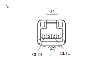
(1) Connect the automatic light control sensor (G1).
|
(2) Check the waveform Use the oscilloscope and check the waveform in the terminal spaces. NOTICE: With the connector connected as is, check from the rear side of the connector. Standard:
If the specified condition is not met, replace the solar sensor. |
|
|
(3) Waveform
The communication waveform changes according to the surrounding brightness. |
|
.png)
 Removal
REMOVAL
CAUTION / NOTICE / HINT
The necessary procedures (adjustment, calibration, initialization or registration)
that must be performed after parts are removed, installed or replaced during the ...
 Installation
INSTALLATION
PROCEDURE
1. INSTALL AUTOMATIC LIGHT CONTROL SENSOR
(a) Engage the claws to install the automatic light control sensor.
(b) ...
Other materials:
Toyota CH-R Service Manual > Oil Cooler: Components
COMPONENTS
ILLUSTRATION
*1
NO. 1 ENGINE UNDER COVER
*2
REAR ENGINE UNDER COVER LH
N*m (kgf*cm, ft.*lbf): Specified torque
-
-
ILLUSTRATION
*1
AIR CLEANER CAP WITH AIR CL ...
Toyota CH-R Service Manual > Safety Connect System: Manual (SOS) Switch Green Indicator Malfunction (B1571)
DESCRIPTION
This DTC is set when the DCM (Telematics Transceiver) detects an open or short
in the manual (SOS) switch green indicator circuit of the manual (SOS) switch. The
manual (SOS) switch green indicator illuminates after the ignition switch turned
to ON.
If the safety connect system i ...
Toyota C-HR (AX20) 2023-2026 Owner's Manual
Toyota CH-R Owners Manual
- For safety and security
- Instrument cluster
- Operation of each component
- Driving
- Interior features
- Maintenance and care
- When trouble arises
- Vehicle specifications
- For owners
Toyota CH-R Service Manual
- Introduction
- Maintenance
- Audio / Video
- Cellular Communication
- Navigation / Multi Info Display
- Park Assist / Monitoring
- Brake (front)
- Brake (rear)
- Brake Control / Dynamic Control Systems
- Brake System (other)
- Parking Brake
- Axle And Differential
- Drive Shaft / Propeller Shaft
- K114 Cvt
- 3zr-fae Battery / Charging
- Networking
- Power Distribution
- Power Assist Systems
- Steering Column
- Steering Gear / Linkage
- Alignment / Handling Diagnosis
- Front Suspension
- Rear Suspension
- Tire / Wheel
- Tire Pressure Monitoring
- Door / Hatch
- Exterior Panels / Trim
- Horn
- Lighting (ext)
- Mirror (ext)
- Window / Glass
- Wiper / Washer
- Door Lock
- Heating / Air Conditioning
- Interior Panels / Trim
- Lighting (int)
- Meter / Gauge / Display
- Mirror (int)
- Power Outlets (int)
- Pre-collision
- Seat
- Seat Belt
- Supplemental Restraint Systems
- Theft Deterrent / Keyless Entry

0.0091