Toyota CH-R Service Manual: Removal
REMOVAL
CAUTION / NOTICE / HINT
HINT:
- Use the same procedure for the RH and LH sides.
- The procedure listed below is for the LH side.
PROCEDURE
1. REMOVE FRONT DOOR INSIDE HANDLE BEZEL PLUG
Click here
.gif)
2. REMOVE MULTIPLEX NETWORK MASTER SWITCH ASSEMBLY WITH FRONT ARMREST BASE UPPER PANEL (for Driver Side)
Click here
3. REMOVE POWER WINDOW REGULATOR SWITCH ASSEMBLY WITH FRONT ARMREST BASE UPPER PANEL (for Front Passenger Side)
Click here
4. REMOVE FRONT DOOR TRIM BOARD SUB-ASSEMBLY
Click here
5. REMOVE FRONT NO. 1 SPEAKER ASSEMBLY
|
(a) Disconnect the connector. |
|
|
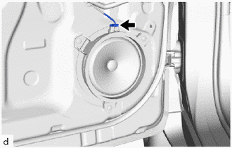
(b) Using a drill bit with a diameter of less than 5 mm (0.197 in.), drill out the 3 rivet heads. NOTICE:
|
|
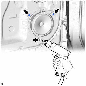
(c) Continue drilling and push out the remaining rivet fragments.
(d) Using a vacuum cleaner, remove the rivet fragments and shavings from the inside of the door.
|
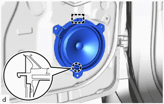
(e) Disengage the claw and guide to remove the front No. 1 speaker assembly. |
|
 Components
COMPONENTS
ILLUSTRATION
*A
for Driver Side
*B
for Front Passenger Side
*1
FRONT DOOR INSIDE HANDLE BEZEL PLUG
*2
...
 Inspection
INSPECTION
PROCEDURE
1. INSPECT FRONT NO. 1 SPEAKER ASSEMBLY
(a) Check the resistance.
(1) Measure the resistance according to the value(s) in the table below.
Standard Resistance:
...
Other materials:
Toyota CH-R Service Manual > Radio Antenna Cord: Removal
REMOVAL
CAUTION / NOTICE / HINT
The necessary procedures (adjustment, calibration, initialization, or registration)
that must be performed after parts are removed and installed, or replaced the during
antenna cord sub-assembly removal/installation are shown below.
Necessary Procedures After P ...
Toyota CH-R Service Manual > Audio And Visual System(for Radio And Display Type): USB Device Malfunction (B1585)
DESCRIPTION
This DTC is stored when a malfunction occurs in a connected device.
DTC No.
Detection Item
DTC Detection Condition
Trouble Area
B1585
USB Device Malfunction
USB Device Malfunction
Non mass- ...
Toyota C-HR (AX20) 2023-2026 Owner's Manual
Toyota CH-R Owners Manual
- For safety and security
- Instrument cluster
- Operation of each component
- Driving
- Interior features
- Maintenance and care
- When trouble arises
- Vehicle specifications
- For owners
Toyota CH-R Service Manual
- Introduction
- Maintenance
- Audio / Video
- Cellular Communication
- Navigation / Multi Info Display
- Park Assist / Monitoring
- Brake (front)
- Brake (rear)
- Brake Control / Dynamic Control Systems
- Brake System (other)
- Parking Brake
- Axle And Differential
- Drive Shaft / Propeller Shaft
- K114 Cvt
- 3zr-fae Battery / Charging
- Networking
- Power Distribution
- Power Assist Systems
- Steering Column
- Steering Gear / Linkage
- Alignment / Handling Diagnosis
- Front Suspension
- Rear Suspension
- Tire / Wheel
- Tire Pressure Monitoring
- Door / Hatch
- Exterior Panels / Trim
- Horn
- Lighting (ext)
- Mirror (ext)
- Window / Glass
- Wiper / Washer
- Door Lock
- Heating / Air Conditioning
- Interior Panels / Trim
- Lighting (int)
- Meter / Gauge / Display
- Mirror (int)
- Power Outlets (int)
- Pre-collision
- Seat
- Seat Belt
- Supplemental Restraint Systems
- Theft Deterrent / Keyless Entry

0.0077