Toyota CH-R Service Manual: Speaker Circuit
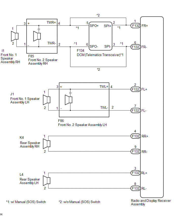
DESCRIPTION
If there is a short in a speaker circuit, the radio and display receiver assembly detects it and stops output to the speakers.
Thus sound cannot be heard from the speakers even if there is no malfunction in the radio and display receiver assembly, DCM (telematics transceiver)*1 or speakers.
- *: w/ Manual (SOS) Switch
WIRING DIAGRAM
CAUTION / NOTICE / HINT
NOTICE:
If the DCM (telematics transceiver) has been replaced, perform the DCM Activation procedure using the Techstream (w/ Manual (SOS) Switch).
Click here
.gif)
PROCEDURE
|
1. |
CHECK SPEAKER (OPERATION CHECK) |
|
(a) Enter the "System Check Mode" screen. Refer to Check Speaker in Operation Check. Click here
|
|
.png)
(b) Perform the operation check above and determine the speaker that is not operating.
|
Not Operating Speaker |
Proceed to |
|---|---|
|
Front No. 1 speaker assembly or front No. 2 speaker assembly (w/ Manual (SOS) Switch) |
A |
|
Front No. 1 speaker assembly or front No. 2 speaker assembly (w/o Manual (SOS) Switch) |
B |
|
Rear speaker assembly |
C |
HINT:
If sound cannot be heard from any speaker, inspect all of them.
| B | .gif) |
GO TO STEP 7 |
| C | |
GO TO STEP 10 |
|
.gif)
|
2. |
CHECK HARNESS AND CONNECTOR (RADIO AND DISPLAY RECEIVER ASSEMBLY - DCM (TELEMATICS TRANSCEIVER) AND FRONT NO. 2 SPEAKER ASSEMBLY) |
(a) Disconnect the F132 radio and display receiver assembly connector.
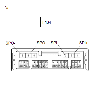
(b) Disconnect the F134 DCM (telematics transceiver) connector.
(c) Disconnect the F85 and F86 front No. 2 speaker assembly connectors.
(d) Measure the resistance according to the value(s) in the table below.
Standard Resistance:
|
Tester Connection |
Condition |
Specified Condition |
|---|---|---|
|
F132-1 (FR+) - F134-2 (SPI+) |
Always |
Below 1 Ω |
|
F132-6 (FR-) - F134-3 (SPI-) |
Always |
Below 1 Ω |
|
F134-5 (SPO+) - F85-4 (TWR+) |
Always |
Below 1 Ω |
|
F134-6 (SPO-) - F85-2 (TWR-) |
Always |
Below 1 Ω |
|
F132-2 (FL+) - F86-4 (TWL+) |
Always |
Below 1 Ω |
|
F132-7 (FL-) - F86-2 (TWL-) |
Always |
Below 1 Ω |
|
F132-1 (FR+) or F134-2 (SPI+) - Body ground |
Always |
10 kΩ or higher |
|
F132-6 (FR-) or F134-3 (SPI-) - Body ground |
Always |
10 kΩ or higher |
|
F134-5 (SPO+) or F85-4 (TWR+) - Body ground |
Always |
10 kΩ or higher |
|
F134-6 (SPO-) or F85-2 (TWR-) - Body ground |
Always |
10 kΩ or higher |
|
F132-2 (FL+) or F86-4 (TWL+) - Body ground |
Always |
10 kΩ or higher |
|
F132-7 (FL-) or F86-2 (TWL-) - Body ground |
Always |
10 kΩ or higher |
| NG | |
REPAIR OR REPLACE HARNESS OR CONNECTOR |
|
|
3. |
CHECK HARNESS AND CONNECTOR (FRONT NO. 1 SPEAKER ASSEMBLY - FRONT NO. 2 SPEAKER ASSEMBLY) |
(a) Disconnect the I1 and J1 front No. 1 speaker assembly connectors.
(b) Disconnect the F85 and F86 front No. 2 speaker assembly connectors.
(c) Measure the resistance according to the value(s) in the table below.
Standard Resistance:
|
Tester Connection |
Condition |
Specified Condition |
|---|---|---|
|
I1-1 - F85-3 (+) |
Always |
Below 1 Ω |
|
I1-2 - F85-1 (-) |
Always |
Below 1 Ω |
|
J1-1 - F86-3 (+) |
Always |
Below 1 Ω |
|
J1-2 - F86-1 (-) |
Always |
Below 1 Ω |
|
I1-1 or F85-3 (+) - Body ground |
Always |
10 kΩ or higher |
|
I1-2 or F85-1 (-) - Body ground |
Always |
10 kΩ or higher |
|
J1-1 or F86-3 (+) - Body ground |
Always |
10 kΩ or higher |
|
J1-2 or F86-1 (-) - Body ground |
Always |
10 kΩ or higher |
| NG | |
REPAIR OR REPLACE HARNESS OR CONNECTOR |
|
|
4. |
INSPECT DCM (TELEMATICS TRANSCEIVER) |
(a) Remove the DCM (telematics transceiver).
Click here
|
(b) Measure the resistance according to the value(s) in the table below. Standard Resistance:
|
|
| NG | |
REPLACE DCM (TELEMATICS TRANSCEIVER) |
|
|
5. |
INSPECT FRONT NO. 2 SPEAKER ASSEMBLY |
(a) Remove the front No. 2 speaker assembly.
Click here
(b) Inspect the front No. 2 speaker assembly.
Click here
(c) Check that the malfunction disappears when a new or known good front No. 2 speaker assembly is installed.
OK:
Malfunction disappears.
| OK | |
END |
|
|
6. |
INSPECT FRONT NO. 1 SPEAKER ASSEMBLY |
(a) Remove the front No. 1 speaker assembly.
Click here
(b) Inspect the front No. 1 speaker assembly.
Click here
| OK | |
PROCEED TO NEXT SUSPECTED AREA SHOWN IN PROBLEM SYMPTOMS TABLE |
| NG | |
REPLACE FRONT NO. 1 SPEAKER ASSEMBLY |
|
7. |
CHECK HARNESS AND CONNECTOR (RADIO AND DISPLAY RECEIVER ASSEMBLY - FRONT NO. 1 SPEAKER ASSEMBLY AND FRONT NO. 2 SPEAKER ASSEMBLY) |
(a) Disconnect the F132 radio and display receiver assembly connector.
(b) Disconnect the I1 and J1 front No. 1 speaker assembly connectors.
(c) Disconnect the F85 and F86 front No. 2 speaker assembly connectors.
(d) Measure the resistance according to the value(s) in the table below.
Standard Resistance:
|
Tester Connection |
Condition |
Specified Condition |
|---|---|---|
|
F132-1 (FR+) - F85-4 (TWR+) |
Always |
Below 1 Ω |
|
F132-6 (FR-) - F85-2 (TWR-) |
Always |
Below 1 Ω |
|
F132-2 (FL+) - F86-4 (TWL+) |
Always |
Below 1 Ω |
|
F132-7 (FL-) - F86-2 (TWL-) |
Always |
Below 1 Ω |
|
I1-1 - F85-3 (+) |
Always |
Below 1 Ω |
|
I1-2 - F85-1 (-) |
Always |
Below 1 Ω |
|
J1-1 - F86-3 (+) |
Always |
Below 1 Ω |
|
J1-2 - F86-1 (-) |
Always |
Below 1 Ω |
|
F132-1 (FR+) or F85-4 (TWR+) - Body ground |
Always |
10 kΩ or higher |
|
F132-6 (FR-) or F85-2 (TWR-) - Body ground |
Always |
10 kΩ or higher |
|
F132-2 (FL+) or F86-4 (TWL+) - Body ground |
Always |
10 kΩ or higher |
|
F132-7 (FL-) or F86-2 (TWL-) - Body ground |
Always |
10 kΩ or higher |
|
I1-1 or F85-3 (+) - Body ground |
Always |
10 kΩ or higher |
|
I1-2 or F85-1 (-) - Body ground |
Always |
10 kΩ or higher |
|
J1-1 or F86-3 (+) - Body ground |
Always |
10 kΩ or higher |
|
J1-2 or F86-1 (-) - Body ground |
Always |
10 kΩ or higher |
| NG | |
REPAIR OR REPLACE HARNESS OR CONNECTOR |
|
|
8. |
INSPECT FRONT NO. 2 SPEAKER ASSEMBLY |
(a) Remove the front No. 2 speaker assembly.
Click here
(b) Inspect the front No. 2 speaker assembly.
Click here
(c) Check that the malfunction disappears when a new or known good front No. 2 speaker assembly is installed.
OK:
Malfunction disappears.
| OK | |
END |
|
|
9. |
INSPECT FRONT NO. 1 SPEAKER ASSEMBLY |
(a) Remove the front No. 1 speaker assembly.
Click here
(b) Inspect the front No. 1 speaker assembly.
Click here
| OK | |
PROCEED TO NEXT SUSPECTED AREA SHOWN IN PROBLEM SYMPTOMS TABLE |
| NG | |
REPLACE FRONT NO. 1 SPEAKER ASSEMBLY |
|
10. |
CHECK HARNESS AND CONNECTOR (RADIO AND DISPLAY RECEIVER ASSEMBLY - REAR SPEAKER ASSEMBLY) |
(a) Disconnect the F132 radio and display receiver assembly connector.
(b) Disconnect the L4 and K4 rear speaker assembly connectors.
(c) Measure the resistance according to the value(s) in the table below.
Standard Resistance:
|
Tester Connection |
Condition |
Specified Condition |
|---|---|---|
|
F132-4 (RR+) - K4-1 |
Always |
Below 1 Ω |
|
F132-9 (RR-) - K4-2 |
Always |
Below 1 Ω |
|
F132-3 (RL+) - L4-1 |
Always |
Below 1 Ω |
|
F132-8 (RL-) - L4-2 |
Always |
Below 1 Ω |
|
F132-4 (RR+) or K4-1 - Body ground |
Always |
10 kΩ or higher |
|
F132-9 (RR-) or K4-2 - Body ground |
Always |
10 kΩ or higher |
|
F132-3 (RL+) or L4-1 - Body ground |
Always |
10 kΩ or higher |
|
F132-8 (RL-) or L4-2 - Body ground |
Always |
10 kΩ or higher |
| NG | |
REPAIR OR REPLACE HARNESS OR CONNECTOR |
|
|
11. |
INSPECT REAR SPEAKER ASSEMBLY |
(a) Remove the rear speaker assembly.
Click here
(b) Inspect the rear speaker assembly.
Click here
| OK | |
PROCEED TO NEXT SUSPECTED AREA SHOWN IN PROBLEM SYMPTOMS TABLE |
| NG | |
REPLACE REAR SPEAKER ASSEMBLY |
 Parking Brake Switch Circuit
DESCRIPTION
This circuit is from the skid control ECU (brake actuator assembly) to the radio
and display receiver assembly.
WIRING DIAGRAM
PROCEDURE
1.
CHECK ELECTRIC PA ...
 Sound Signal Circuit between Radio Receiver and Stereo Jack Adapter
DESCRIPTION
The No. 1 stereo jack adapter assembly sends the sound signal from an external
device to the radio and display receiver assembly via this circuit.
The sound signal that has been sent i ...
Other materials:
Toyota CH-R Service Manual > Roof Headlining: Disassembly
DISASSEMBLY
PROCEDURE
1. REMOVE ROOF HEADLINING FORMING PAD (except Cold Area)
(a) Remove the 2 roof headlining forming pads.
2. REMOVE NO. 1 ROOF SILENCER PAD
(a) Remove the No. 1 roof silencer pad.
3. REMOVE NO. 2 ROOF SILENCER PAD
(a) Remove the 2 No. 2 roof silencer pads.
4. REMOVE ...
Toyota CH-R Service Manual > Audio And Visual System(for Radio Receiver Type): Cellular Phone Inspection
CAUTION / NOTICE / HINT
HINT:
If the operation of a cellular phone or the radio receiver assembly is requested,
make sure to follow the instructions closely and perform the operation.
PROCEDURE
1.
CHECK USAGE CONDITION
(a) Check that the vehicle and cellular ph ...
Toyota C-HR (AX20) 2023-2026 Owner's Manual
Toyota CH-R Owners Manual
- For safety and security
- Instrument cluster
- Operation of each component
- Driving
- Interior features
- Maintenance and care
- When trouble arises
- Vehicle specifications
- For owners
Toyota CH-R Service Manual
- Introduction
- Maintenance
- Audio / Video
- Cellular Communication
- Navigation / Multi Info Display
- Park Assist / Monitoring
- Brake (front)
- Brake (rear)
- Brake Control / Dynamic Control Systems
- Brake System (other)
- Parking Brake
- Axle And Differential
- Drive Shaft / Propeller Shaft
- K114 Cvt
- 3zr-fae Battery / Charging
- Networking
- Power Distribution
- Power Assist Systems
- Steering Column
- Steering Gear / Linkage
- Alignment / Handling Diagnosis
- Front Suspension
- Rear Suspension
- Tire / Wheel
- Tire Pressure Monitoring
- Door / Hatch
- Exterior Panels / Trim
- Horn
- Lighting (ext)
- Mirror (ext)
- Window / Glass
- Wiper / Washer
- Door Lock
- Heating / Air Conditioning
- Interior Panels / Trim
- Lighting (int)
- Meter / Gauge / Display
- Mirror (int)
- Power Outlets (int)
- Pre-collision
- Seat
- Seat Belt
- Supplemental Restraint Systems
- Theft Deterrent / Keyless Entry

0.009