Toyota CH-R Service Manual: USB Audio System Recognition/Play Error
DESCRIPTION
When a USB device or "iPod" is connected to the USB jack of the No. 1 stereo jack adapter assembly, it must have playable files. The device must also communicate with and be recognized by the radio and display receiver assembly. This diagnostic procedure is for when a device is not recognized, or files from the device cannot be played normally.
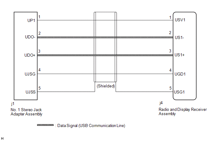
WIRING DIAGRAM
CAUTION / NOTICE / HINT
NOTICE:
- Depending on the parts that are replaced during vehicle inspection or
maintenance, performing initialization, registration or calibration may
be needed. Refer to Precaution for Audio and Visual System.
Click here
.gif)
- When replacing the radio and display receiver assembly, always replace
it with a new one. If a radio and display receiver assembly which was installed
to another vehicle is used, the following may occurs:
- A communication malfunction DTC may be stored.
- The radio and display receiver assembly may not operate normally.
HINT:
- When a large amount of data is in a USB device, it may take a while to begin playback.
- When using a USB device, files that are copy protection or encrypted due to copyright reasons cannot be played.
- When files are not played in the sorted order, perform the following
procedure before inspection.
- Add numbers in front of the file names.
- Put the files in a folder and copy the folder data to the USB device.
PROCEDURE
|
1. |
CHECK USB DEVICE OR "iPod" |
(a) Disconnect the USB device or "iPod" from the No. 1 stereo jack adapter assembly.
(b) Check if playable files are present on the USB device or "iPod".
HINT:
Refer to System Description for playable files.
Click here
(c) Check if the USB device is a compatible format or "iPod" is a compatible version.
HINT:
Refer to System Description for compatible formats and versions.
Click here
|
Result |
Proceed to |
|---|---|
|
No playable files exist, or incompatible device format or version. |
A |
|
Playable files exist, and compatible device format or version. |
B |
| A | .gif) |
END (USB DEVICE FORMAT WAS INCOMPATIBLE, "iPod" VERSION IS INCOMPATIBLE, OR NO PLAYABLE FILES EXIST) |
|
.gif)
|
2. |
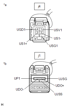
CHECK HARNESS AND CONNECTOR (RADIO AND DISPLAY RECEIVER ASSEMBLY - NO. 1 STEREO JACK ADAPTER ASSEMBLY) |
(a) Disconnect the radio and display receiver assembly connector.
(b) Disconnect the No. 1 stereo jack adapter assembly connector.
|
(c) Measure the resistance according to the value(s) in the table below. Standard Resistance:
|
|
| NG | |
REPAIR OR REPLACE HARNESS OR CONNECTOR |
|
|
3. |
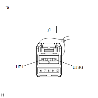
INSPECT RADIO AND DISPLAY RECEIVER ASSEMBLY (NO. 1 STEREO JACK ADAPTER ASSEMBLY POWER SOURCE) |
(a) Reconnect the j4 radio and display receiver assembly connector.
|
(b) Measure the voltage according to the value(s) in the table below. Standard Voltage:
|
|
| NG | |
REPLACE RADIO AND DISPLAY RECEIVER ASSEMBLY |
|
|
4. |
FORMAT USB DEVICE OR RESTORE "iPod" AND RECHECK |
(a) Delete all files in the USB device or "iPod" and format/restore it.
(b) Save the data again and check if it can be played on the in-vehicle device.
NOTICE:
Formatting a USB device or restoring an "iPod" erases all music on the device. Ensure that a backup of the music data is available before performing this operation.
OK:
Malfunction disappears.
| OK | |
END (USB OR "iPod" WAS DEFECTIVE) |
|
|
5. |
REPLACE USB DEVICE OR "iPod" |
(a) Turn the ignition switch off.
HINT:
When this malfunction occurs, it is necessary to turn the ignition switch off to make it possible for the vehicle to recognize a new device when it is connected.
(b) Turn the ignition switch to ACC.
(c) Connect a known good USB device or "iPod" to the No. 1 stereo jack adapter assembly.
HINT:
- If the malfunction occurred when a USB device was in use, use another USB device for the inspection. If the malfunction occurred when an "iPod" was in use, use another "iPod" for the inspection.
- Refer to System Description for compatible formats and versions.
Click here
|
|
6. |
CHECK USB DEVICE OR "iPod" |
(a) Check if a USB device or "iPod" is recognized by the radio and display receiver assembly, and if information such as track, artist and album names is displayed on the screen.
OK:
USB device or "iPod" is recognized properly and the information is displayed on the screen.
| OK | |
USB DEVICE OR "iPod" WAS INCOMPATIBLE OR DEFECTIVE |
| NG | |
PROCEED TO NEXT SUSPECTED AREA SHOWN IN PROBLEM SYMPTOMS TABLE |
 Portable Player cannot be Registered
CAUTION / NOTICE / HINT
HINT:
Some versions of "Bluetooth" compatible audio players may not function, or the
functions may be limited using the radio and display receiver assembly, even ...
 Black Screen
PROCEDURE
1.
CHECK DISPLAY SETTING
(a) Check that the display is not in screen off mode.
OK:
The display setting is not in screen off mode.
NG
...
Other materials:
Toyota CH-R Service Manual > Rear Door: Reassembly
REASSEMBLY
CAUTION / NOTICE / HINT
HINT:
Use the same procedure for the RH side and LH side.
The following procedure is for the LH side.
PROCEDURE
1. INSTALL REAR DOOR OUTSIDE STRIPE
Click here
2. INSTALL REAR DOOR LOWER OUTSIDE STRIPE
Click here
3. INSTALL REAR DO ...
Toyota CH-R Service Manual > Front Door Outside Moulding: Reassembly
REASSEMBLY
CAUTION / NOTICE / HINT
HINT:
Use the same procedure for the RH and LH sides.
The procedure listed below is for the LH side.
PROCEDURE
1. INSTALL OUTSIDE MOULDING RETAINER
(a) When using a new front door outside moulding:
(1) Clean the surface of the front door ou ...
Toyota C-HR (AX20) 2023-2026 Owner's Manual
Toyota CH-R Owners Manual
- For safety and security
- Instrument cluster
- Operation of each component
- Driving
- Interior features
- Maintenance and care
- When trouble arises
- Vehicle specifications
- For owners
Toyota CH-R Service Manual
- Introduction
- Maintenance
- Audio / Video
- Cellular Communication
- Navigation / Multi Info Display
- Park Assist / Monitoring
- Brake (front)
- Brake (rear)
- Brake Control / Dynamic Control Systems
- Brake System (other)
- Parking Brake
- Axle And Differential
- Drive Shaft / Propeller Shaft
- K114 Cvt
- 3zr-fae Battery / Charging
- Networking
- Power Distribution
- Power Assist Systems
- Steering Column
- Steering Gear / Linkage
- Alignment / Handling Diagnosis
- Front Suspension
- Rear Suspension
- Tire / Wheel
- Tire Pressure Monitoring
- Door / Hatch
- Exterior Panels / Trim
- Horn
- Lighting (ext)
- Mirror (ext)
- Window / Glass
- Wiper / Washer
- Door Lock
- Heating / Air Conditioning
- Interior Panels / Trim
- Lighting (int)
- Meter / Gauge / Display
- Mirror (int)
- Power Outlets (int)
- Pre-collision
- Seat
- Seat Belt
- Supplemental Restraint Systems
- Theft Deterrent / Keyless Entry

0.0095