Toyota CH-R Service Manual: Removal
REMOVAL
CAUTION / NOTICE / HINT
The necessary procedures (adjustment, calibration, initialization, or registration) that must be performed after parts are removed and installed, or replaced during rear shock absorber assembly removal/installation are shown below.
Necessary Procedures After Parts Removed/Installed/Replaced|
Replaced Part or Performed Procedure |
Necessary Procedure |
Effect/Inoperative Function when Necessary Procedure not Performed |
Link |
|---|---|---|---|
|
Rear wheel alignment adjustment |
|
|
|
|
Removal/installation of rear height control sensor sub-assembly LH*1 |
Initialize headlight ECU sub-assembly LH |
Automatic headlight beam level control system |
|
|
Suspension, tires, etc. (The vehicle height changes because of suspension or tire replacement)*1 |
- *1: w/ Height Control Sensor
HINT:
- Use the same procedure for the RH side and LH side.
- The following procedure is for the LH side.
PROCEDURE
1. REMOVE REAR WHEEL
Click here
.gif)
2. REMOVE REAR HEIGHT CONTROL SENSOR SUB-ASSEMBLY LH (w/ Height Control Sensor)
Click here
3. SEPARATE REAR SHOCK ABSORBER ASSEMBLY
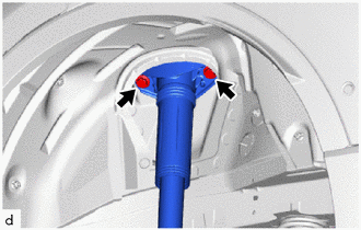
|
(a) Remove the 2 bolts and separate the rear shock absorber assembly from the vehicle. |
|
4. LOOSEN REAR SHOCK ABSORBER ASSEMBLY
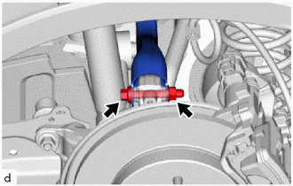
|
(a) Loosen the nut of the rear shock absorber assembly. NOTICE: Hold the rear axle carrier pin while rotating the nut. |
|
5. REMOVE REAR STABILIZER LINK ASSEMBLY
Click here
6. SEPARATE REAR UPPER CONTROL ARM ASSEMBLY
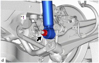
|
(a) Remove the bolt and nut, and separate the rear upper control arm assembly from the rear axle carrier sub-assembly. NOTICE: Because the nut has its own stopper, do not turn the nut. Loosen the bolt with the nut secured. |
|
7. REMOVE REAR SHOCK ABSORBER ASSEMBLY
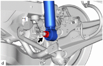
|
(a) Remove the nut and rear shock absorber assembly from the rear axle carrier sub-assembly. NOTICE: Hold the rear axle carrier pin while rotating the nut. |
|
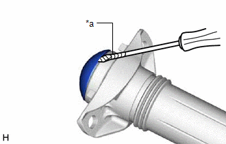
8. REMOVE REAR SHOCK ABSORBER CAP
|
(a) Using a screwdriver with its tip wrapped with protective tape, remove the rear shock absorber cap from the rear shock absorber assembly. |
|
9. REMOVE REAR SUSPENSION SUPPORT ASSEMBLY
|
(a) Secure the rear shock absorber assembly in a vise using aluminum plates. NOTICE: Do not overtighten the vise. |
|
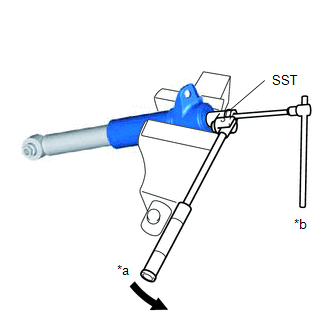
(b) Using SST and a 6 mm hexagon socket wrench, hold the rear shock absorber rod and remove the rear support to rear shock absorber nut.
SST: 09729-97202
(c) Remove the rear suspension support assembly from the rear shock absorber assembly.
 Components
COMPONENTS
ILLUSTRATION
*1
REAR SHOCK ABSORBER ASSEMBLY
*2
REAR STABILIZER LINK ASSEMBLY
*3
REAR UPPER CONTROL ARM ASSEMBLY
...
 Inspection
INSPECTION
PROCEDURE
1. INSPECT REAR SHOCK ABSORBER ASSEMBLY
(a) Compress and extend the rear shock absorber assembly rod 4 or more times.
Standard:
When compressed and extended at a constant sp ...
Other materials:
Toyota CH-R Owners Manual > Multi-information display: Settings display
The settings of the following items can be changed.
For functions that can be enabled or disabled, the function switches between
on and off each time
is
pressed.
LDA (Lane Departure Alert)
Select to set up the following items.
Steering Assist on/off
Alert sensitivity
...
Toyota CH-R Service Manual > Smart Key System(for Entry Function): Diagnosis System
DIAGNOSIS SYSTEM
DESCRIPTION
(a) Smart key system (for Entry Function) data and Diagnostic Trouble Codes (DTCs)
can be read through the vehicle Data Link Connector 3 (DLC3). In some cases, a malfunction
may be occurring in the smart key system. When the system seems to be malfunctioning,
use ...
Toyota C-HR (AX20) 2023-2026 Owner's Manual
Toyota CH-R Owners Manual
- For safety and security
- Instrument cluster
- Operation of each component
- Driving
- Interior features
- Maintenance and care
- When trouble arises
- Vehicle specifications
- For owners
Toyota CH-R Service Manual
- Introduction
- Maintenance
- Audio / Video
- Cellular Communication
- Navigation / Multi Info Display
- Park Assist / Monitoring
- Brake (front)
- Brake (rear)
- Brake Control / Dynamic Control Systems
- Brake System (other)
- Parking Brake
- Axle And Differential
- Drive Shaft / Propeller Shaft
- K114 Cvt
- 3zr-fae Battery / Charging
- Networking
- Power Distribution
- Power Assist Systems
- Steering Column
- Steering Gear / Linkage
- Alignment / Handling Diagnosis
- Front Suspension
- Rear Suspension
- Tire / Wheel
- Tire Pressure Monitoring
- Door / Hatch
- Exterior Panels / Trim
- Horn
- Lighting (ext)
- Mirror (ext)
- Window / Glass
- Wiper / Washer
- Door Lock
- Heating / Air Conditioning
- Interior Panels / Trim
- Lighting (int)
- Meter / Gauge / Display
- Mirror (int)
- Power Outlets (int)
- Pre-collision
- Seat
- Seat Belt
- Supplemental Restraint Systems
- Theft Deterrent / Keyless Entry

0.012