Toyota CH-R Service Manual: Unlock Warning Switch Circuit
DESCRIPTION
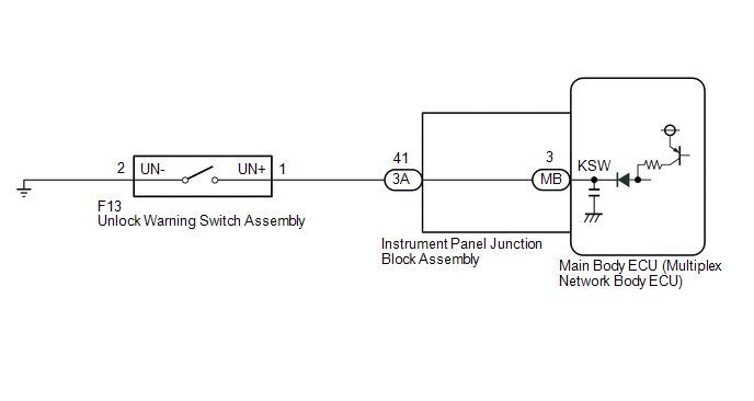
The key unlock warning switch assembly comes on when the ignition key is inserted into the ignition key cylinder and goes off when the ignition key is removed.
WIRING DIAGRAM
PROCEDURE
|
1. |
READ VALUE USING TECHSTREAM (KEY UNLOCK WARNING SW) |
(a) Connect the Techstream to the DLC3.
(b) Turn the ignition switch to ON.
(c) Turn the Techstream on.
(d) Enter the following menus: Body Electrical / Main Body / Data List.
(e) According to the display on the Techstream, read the Data List.
Body Electrical > Main Body > Data List|
Tester Display |
Measurement Item |
Range |
Normal Condition |
Diagnostic Note |
|---|---|---|---|---|
|
Key Unlock Warning SW |
Unlock warning switch |
ON or OFF |
ON: Key is inserted into ignition key cylinder OFF: Key is removed from ignition key cylinder |
- |
|
Tester Display |
|---|
|
Key Unlock Warning SW |
OK:
When the key is in the ignition key cylinder, "ON" appears on the screen.
| OK | .gif) |
PROCEED TO NEXT SUSPECTED AREA SHOWN IN PROBLEM SYMPTOMS TABLE |
|
.gif)
|
2. |
INSPECT UNLOCK WARNING SWITCH ASSEMBLY |
(a) Remove the unlock warning switch assembly.
Click here .gif)
(b) Inspect the unlock warning switch assembly.
Click here
| NG | |
REPLACE UNLOCK WARNING SWITCH ASSEMBLY |
|
|
3. |
CHECK HARNESS AND CONNECTOR (INSTRUMENT PANEL JUNCTION BLOCK ASSEMBLY - UNLOCK WARNING SWITCH ASSEMBLY - BODY GROUND) |
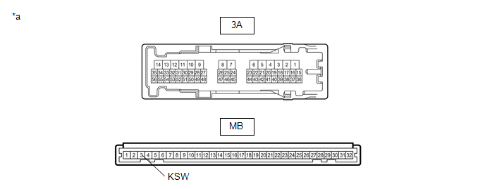
(a) Disconnect the 3A instrument panel junction block assembly connector.
(b) Disconnect the F13 unlock warning switch assembly connector.
(c) Measure the resistance according to the value(s) in the table below.
Standard Resistance:
|
Tester Connection |
Condition |
Specified Condition |
|---|---|---|
|
3A-41 - F13-1 (UN+) |
Always |
Below 1 Ω |
|
3A-41 or F13-1 (UN+) - Body ground |
Always |
10 kΩ or higher |
|
F13-2 (UN-) - Body ground |
Always |
Below 1 Ω |
| NG | |
REPAIR OR REPLACE HARNESS OR CONNECTOR |
|
|
4. |
INSPECT INSTRUMENT PANEL JUNCTION BLOCK ASSEMBLY |
(a) Remove the main body ECU (multiplex network body ECU).
Click here
|
*a |
Component without harness connected (Instrument Panel Junction Block Assembly) |
- |
- |
(b) Disconnect the 3A instrument panel junction block assembly connector.
(c) Measure the resistance according to the value(s) in the table below.
Standard Resistance:
|
Tester Connection |
Condition |
Specified Condition |
|---|---|---|
|
3A-41 - MB-3 (KSW) |
Always |
Below 1 Ω |
| OK | |
REPLACE MAIN BODY ECU (MULTIPLEX NETWORK BODY ECU) |
| NG | |
REPLACE INSTRUMENT PANEL JUNCTION BLOCK ASSEMBLY |
 Power Source Circuit
DESCRIPTION
Based on changes in the power source voltage, the main body ECU (multiplex network
body ECU) can detect if the battery has been disconnected and reconnected.
WIRING DIAGRAM
CAUTION ...
 Transponder Key Amplifier
Components
COMPONENTS
ILLUSTRATION
*1
LOWER STEERING COLUMN COVER
*2
TRANSPONDER KEY COIL
*3
UNLOCK WARNING SWITCH ASSEMB ...
Other materials:
Toyota CH-R Service Manual > Lin Communication System: LIN Communication Bus Malfunction (B2325)
DESCRIPTION
If the main body ECU (multiplex network body ECU) detects a communication error
with an ECU connected to the door bus lines for 7 seconds or more, DTC B2325 will
be stored.
DTC No.
Detection Item
DTC Detection Condition
Trouble Area
...
Toyota CH-R Service Manual > Lighting System: Interior Light Circuit
DESCRIPTION
The main body ECU (multiplex network body ECU) controls the operation of the
following lights:
Map Light Assembly
No. 1 Room Light Assembly
WIRING DIAGRAM
CAUTION / NOTICE / HINT
NOTICE:
Inspect the fuses for circuits related to this system before perfo ...
Toyota C-HR (AX20) 2023-2026 Owner's Manual
Toyota CH-R Owners Manual
- For safety and security
- Instrument cluster
- Operation of each component
- Driving
- Interior features
- Maintenance and care
- When trouble arises
- Vehicle specifications
- For owners
Toyota CH-R Service Manual
- Introduction
- Maintenance
- Audio / Video
- Cellular Communication
- Navigation / Multi Info Display
- Park Assist / Monitoring
- Brake (front)
- Brake (rear)
- Brake Control / Dynamic Control Systems
- Brake System (other)
- Parking Brake
- Axle And Differential
- Drive Shaft / Propeller Shaft
- K114 Cvt
- 3zr-fae Battery / Charging
- Networking
- Power Distribution
- Power Assist Systems
- Steering Column
- Steering Gear / Linkage
- Alignment / Handling Diagnosis
- Front Suspension
- Rear Suspension
- Tire / Wheel
- Tire Pressure Monitoring
- Door / Hatch
- Exterior Panels / Trim
- Horn
- Lighting (ext)
- Mirror (ext)
- Window / Glass
- Wiper / Washer
- Door Lock
- Heating / Air Conditioning
- Interior Panels / Trim
- Lighting (int)
- Meter / Gauge / Display
- Mirror (int)
- Power Outlets (int)
- Pre-collision
- Seat
- Seat Belt
- Supplemental Restraint Systems
- Theft Deterrent / Keyless Entry

0.0079