Toyota CH-R Service Manual: Transponder Key Amplifier
Components
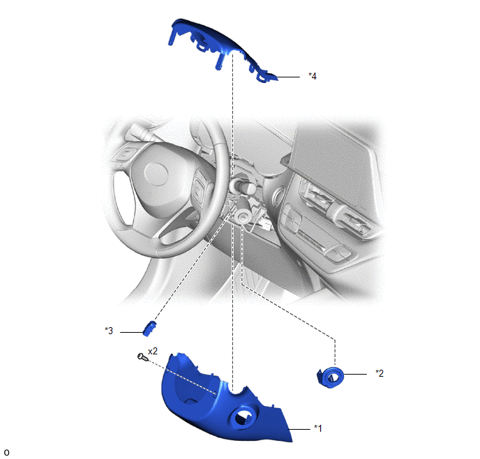
COMPONENTS
ILLUSTRATION
|
*1 |
LOWER STEERING COLUMN COVER |
*2 |
TRANSPONDER KEY COIL |
|
*3 |
UNLOCK WARNING SWITCH ASSEMBLY |
*4 |
UPPER STEERING COLUMN COVER |
Removal
REMOVAL
PROCEDURE
1. REMOVE LOWER STEERING COLUMN COVER
Click here .gif)
2. REMOVE UPPER STEERING COLUMN COVER
Click here
3. REMOVE UNLOCK WARNING SWITCH ASSEMBLY
Click here
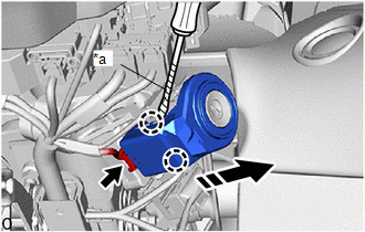
4. REMOVE TRANSPONDER KEY COIL
(a) Disconnect the connector.
|
*a |
Protective Tape |
.png) |
Remove in this Direction |
(b) Using a screwdriver with its tip wrapped in protective tape, disengage the claws to remove the transponder key coil as shown in the illustration.
Installation
INSTALLATION
PROCEDURE
1. INSTALL TRANSPONDER KEY COIL
(a) Engage the claws to install the transponder key coil as shown in the illustration.
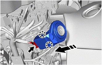
.png) |
Install in this Direction |
(b) Connect the connector.
2. INSTALL UNLOCK WARNING SWITCH ASSEMBLY
Click here .gif)
3. INSTALL UPPER STEERING COLUMN COVER
Click here
4. INSTALL LOWER STEERING COLUMN COVER
Click here
 Unlock Warning Switch Circuit
DESCRIPTION
The key unlock warning switch assembly comes on when the ignition key is inserted
into the ignition key cylinder and goes off when the ignition key is removed.
WIRING DIAGRAM
PROCED ...

Other materials:
Toyota CH-R Service Manual > K114 Cvt: Torque Converter And Drive Plate
Inspection
INSPECTION
PROCEDURE
1. INSPECT TORQUE CONVERTER ASSEMBLY
(a) Inspect the one-way clutch.
(1) Press on the spline of the stator with a finger and rotate the spline.
Check that the spline rotates smoothly when turned clockwise and rotates
with difficulty when tu ...
Toyota CH-R Service Manual > Continuously Variable Transaxle System: Check Mode Procedure
CHECK MODE PROCEDURE
DESCRIPTION
(a) Check mode has a higher sensitivity to malfunctions and can detect malfunctions
that cannot be detected in normal mode. Check mode can also detect all the malfunctions
that can be detected in normal mode. In check mode, DTCs are stored with 1 trip
detecti ...
Toyota C-HR (AX20) 2023-2026 Owner's Manual
Toyota CH-R Owners Manual
- For safety and security
- Instrument cluster
- Operation of each component
- Driving
- Interior features
- Maintenance and care
- When trouble arises
- Vehicle specifications
- For owners
Toyota CH-R Service Manual
- Introduction
- Maintenance
- Audio / Video
- Cellular Communication
- Navigation / Multi Info Display
- Park Assist / Monitoring
- Brake (front)
- Brake (rear)
- Brake Control / Dynamic Control Systems
- Brake System (other)
- Parking Brake
- Axle And Differential
- Drive Shaft / Propeller Shaft
- K114 Cvt
- 3zr-fae Battery / Charging
- Networking
- Power Distribution
- Power Assist Systems
- Steering Column
- Steering Gear / Linkage
- Alignment / Handling Diagnosis
- Front Suspension
- Rear Suspension
- Tire / Wheel
- Tire Pressure Monitoring
- Door / Hatch
- Exterior Panels / Trim
- Horn
- Lighting (ext)
- Mirror (ext)
- Window / Glass
- Wiper / Washer
- Door Lock
- Heating / Air Conditioning
- Interior Panels / Trim
- Lighting (int)
- Meter / Gauge / Display
- Mirror (int)
- Power Outlets (int)
- Pre-collision
- Seat
- Seat Belt
- Supplemental Restraint Systems
- Theft Deterrent / Keyless Entry

0.01