Toyota CH-R Service Manual: System Diagram
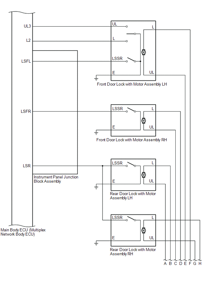
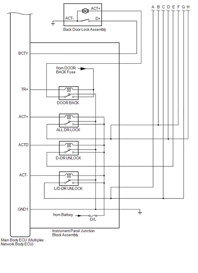
SYSTEM DIAGRAM
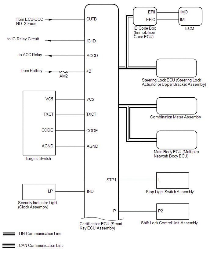
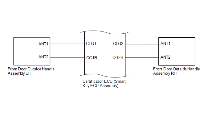
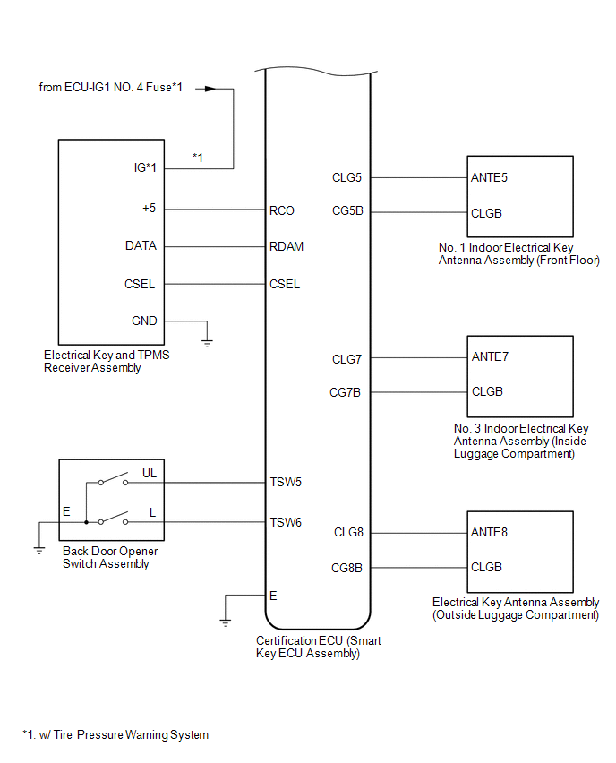
- This is a detailed diagram related to the certification ECU (smart key
ECU assembly).
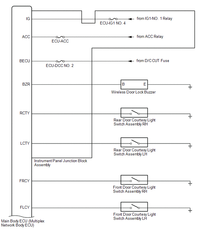
- This is a detailed diagram related to the main body ECU (multiplex network
body ECU).
|
Component |
Function |
|---|---|
|
Front door outside handle assembly |
Receives request signals from the certification ECU (smart key ECU assembly) via the built-in electrical key antenna (front door) and forms the vehicle exterior detection area. Uses the built-in touch sensor (lock sensor/unlock sensor) to detect the operation of the front door outside handle assembly and sends signals to the certification ECU (smart key ECU assembly). |
|
No. 1 indoor electrical key antenna assembly (front floor) No. 3 indoor electrical key antenna assembly (inside luggage compartment) |
Receives the request code from the certification ECU (smart key ECU assembly) and forms the vehicle interior detection area. |
|
Electrical key antenna (outside luggage compartment) |
Receives the request code from the certification ECU (smart key ECU assembly) and forms the back door exterior detection area. |
|
Back door opener switch assembly |
Sends switch operation signals to the certification ECU (smart key ECU assembly). |
|
Electrical key and TPMS receiver assembly |
Receives the smart key system code/wireless code sent from the electrical key transmitter sub-assembly and sends it to the certification ECU (smart key ECU assembly). |
|
Wireless door lock buzzer |
Sounds when warning functions operate in accordance with certification ECU (smart key ECU assembly) control. |
|
Electrical key transmitter sub-assembly |
Sends the ID code upon receiving a request signal. |
|
Certification ECU (smart key ECU assembly) |
Sends request codes to each electrical key antenna. Distinguishes and verifies the ID code from the electrical key transmitter sub-assembly and sends signals to each ECU in response to operated functions (controls entire system). Performs encryption code communication with the ID code box (immobiliser code ECU) when ignition operations are performed. |
 Parts Location
PARTS LOCATION
ILLUSTRATION
*1
ECM
-
-
ILLUSTRATION
*1
BACK DOOR COURTESY SWITCH
*2
BACK DOOR L ...
 How To Proceed With Troubleshooting
CAUTION / NOTICE / HINT
HINT:
Use these procedures to troubleshoot the smart key system (for Entry
Function).
*: Use the Techstream.
PROCEDURE
1.
VEHIC ...
Other materials:
Toyota CH-R Service Manual > Navigation System: Precaution
PRECAUTION
PRECAUTION FOR NAVIGATION SYSTEM
NOTICE:
When replacing the radio and display receiver assembly or navigation
ECU, always replace it with a new one. If a radio and display receiver assembly
or navigation ECU which was installed to another vehicle is used, the following ...
Toyota CH-R Service Manual > Brake Actuator: Precaution
PRECAUTION
IGNITION SWITCH EXPRESSIONS
(a) The type of ignition switch used on this model differs depending on the specifications
of the vehicle. The expressions listed in the table below are used in this section.
Expression
Ignition Switch (Position)
Engine Swi ...
Toyota C-HR (AX20) 2023-2026 Owner's Manual
Toyota CH-R Owners Manual
- For safety and security
- Instrument cluster
- Operation of each component
- Driving
- Interior features
- Maintenance and care
- When trouble arises
- Vehicle specifications
- For owners
Toyota CH-R Service Manual
- Introduction
- Maintenance
- Audio / Video
- Cellular Communication
- Navigation / Multi Info Display
- Park Assist / Monitoring
- Brake (front)
- Brake (rear)
- Brake Control / Dynamic Control Systems
- Brake System (other)
- Parking Brake
- Axle And Differential
- Drive Shaft / Propeller Shaft
- K114 Cvt
- 3zr-fae Battery / Charging
- Networking
- Power Distribution
- Power Assist Systems
- Steering Column
- Steering Gear / Linkage
- Alignment / Handling Diagnosis
- Front Suspension
- Rear Suspension
- Tire / Wheel
- Tire Pressure Monitoring
- Door / Hatch
- Exterior Panels / Trim
- Horn
- Lighting (ext)
- Mirror (ext)
- Window / Glass
- Wiper / Washer
- Door Lock
- Heating / Air Conditioning
- Interior Panels / Trim
- Lighting (int)
- Meter / Gauge / Display
- Mirror (int)
- Power Outlets (int)
- Pre-collision
- Seat
- Seat Belt
- Supplemental Restraint Systems
- Theft Deterrent / Keyless Entry

0.0077