Toyota CH-R Service Manual: System Diagram
SYSTEM DIAGRAM
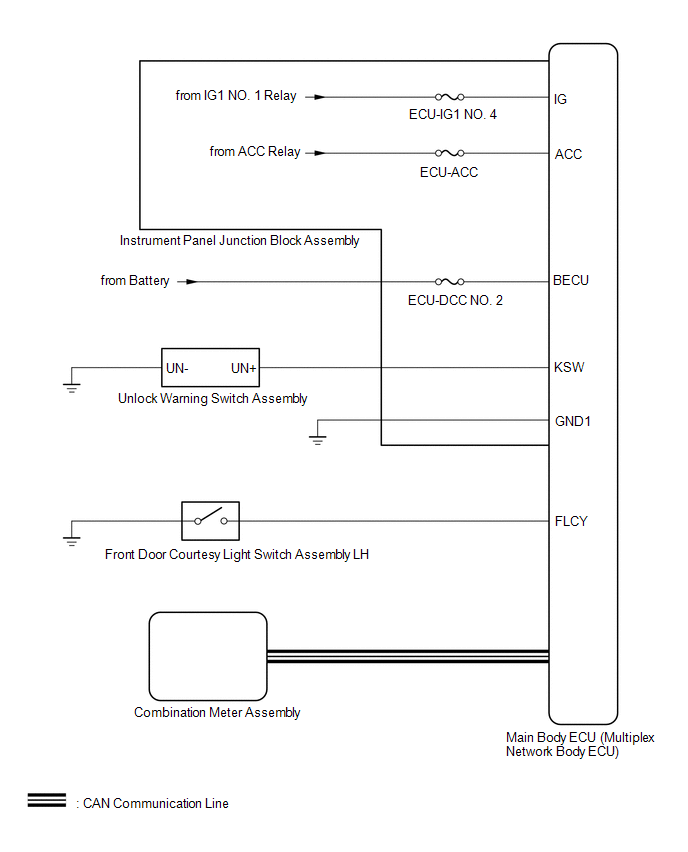
Key Reminder Warning System
 Communication Table
|
Sender |
Receiver |
Signal |
Line |
|---|---|---|---|
|
Main Body ECU (Multiplex Network Body ECU) |
Combination Meter Assembly |
Driver door courtesy light switch signal |
CAN |
|
Unlock warning switch signal |
 Precaution
PRECAUTION
PRECAUTION WHEN REPLACING COMBINATION METER ASSEMBLY
(a) When replacing the combination meter assembly, always replace it with a new
one. If a combination meter assembly which was insta ...
 System Description
SYSTEM DESCRIPTION
KEY REMINDER WARNING SYSTEM DESCRIPTION
(a) When the driver door is opened with the ignition switch off or ACC, this
system causes a buzzer to sound in order to warn the driver ...
Other materials:
Toyota CH-R Service Manual > Automatic High Beam System: Diagnostic Trouble Code Chart
DIAGNOSTIC TROUBLE CODE CHART
Automatic High Beam System
DTC No.
Detection Item
Link
B124B
Automatic High Beam System
B124C
Automatic High Beam Camera
U ...
Toyota CH-R Service Manual > Steering Gear: Installation
INSTALLATION
PROCEDURE
1. INSTALL TIE ROD END SUB-ASSEMBLY LH
(a) Install the lock nut and tie rod end sub-assembly LH to the steering
gear assembly until the matchmarks are aligned.
HINT:
After adjusting the toe-in, tighten the lock nut.
...
Toyota C-HR (AX20) 2023-2026 Owner's Manual
Toyota CH-R Owners Manual
- For safety and security
- Instrument cluster
- Operation of each component
- Driving
- Interior features
- Maintenance and care
- When trouble arises
- Vehicle specifications
- For owners
Toyota CH-R Service Manual
- Introduction
- Maintenance
- Audio / Video
- Cellular Communication
- Navigation / Multi Info Display
- Park Assist / Monitoring
- Brake (front)
- Brake (rear)
- Brake Control / Dynamic Control Systems
- Brake System (other)
- Parking Brake
- Axle And Differential
- Drive Shaft / Propeller Shaft
- K114 Cvt
- 3zr-fae Battery / Charging
- Networking
- Power Distribution
- Power Assist Systems
- Steering Column
- Steering Gear / Linkage
- Alignment / Handling Diagnosis
- Front Suspension
- Rear Suspension
- Tire / Wheel
- Tire Pressure Monitoring
- Door / Hatch
- Exterior Panels / Trim
- Horn
- Lighting (ext)
- Mirror (ext)
- Window / Glass
- Wiper / Washer
- Door Lock
- Heating / Air Conditioning
- Interior Panels / Trim
- Lighting (int)
- Meter / Gauge / Display
- Mirror (int)
- Power Outlets (int)
- Pre-collision
- Seat
- Seat Belt
- Supplemental Restraint Systems
- Theft Deterrent / Keyless Entry

0.0097