Toyota CH-R Service Manual: Security Horn Assembly
Components
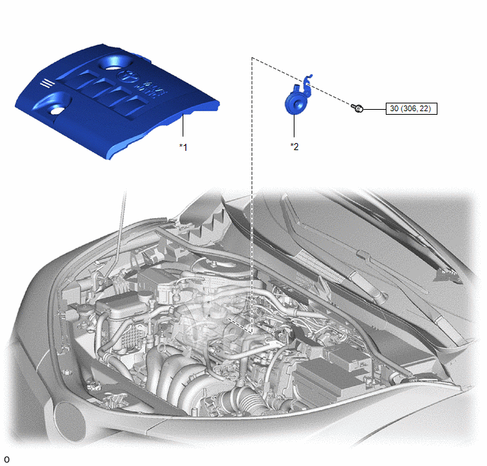
COMPONENTS
ILLUSTRATION
|
*1 |
NO. 2 CYLINDER HEAD COVER |
*2 |
SECURITY HORN ASSEMBLY |
.png) |
N*m (kgf*cm, ft.*lbf): Specified torque |
- |
- |
Removal
REMOVAL
PROCEDURE
1. REMOVE NO. 2 CYLINDER HEAD COVER
Click here .gif)
2. REMOVE SECURITY HORN ASSEMBLY
|
(a) Remove the bolt. |
|
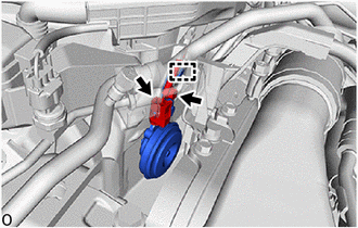
(b) Disengage the guide to remove the security horn assembly.
(c) Disconnect the connector.
Inspection
INSPECTION
PROCEDURE
1. INSPECT SECURITY HORN ASSEMBLY
|
(a) Check the operation. (1) Apply battery voltage and check the operation of the security horn assembly. OK:
If the result is not as specified, replace the security horn assembly. |
|
Installation
INSTALLATION
PROCEDURE
1. INSTALL SECURITY HORN ASSEMBLY
|
(a) Connect the connector. |
|
.png)
(b) Engage the guide to install the security horn assembly.
(c) Install the bolt.
Torque:
30 N·m {306 kgf·cm, 22 ft·lbf}
2. INSTALL NO. 2 CYLINDER HEAD COVER
Click here .gif)
 Relay
Relay
Inspection
INSPECTION
PROCEDURE
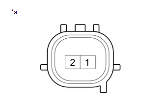
1. INSPECT SECURITY WARNING RELAY
(a) Check the resistance.
(1) Measure the resistance according to the value(s) in the table below.
Standard Res ...

Other materials:
Toyota CH-R Service Manual > Transmission Control Cable: Removal
REMOVAL
CAUTION / NOTICE / HINT
The necessary procedures (adjustment, calibration, initialization, or registration)
that must be performed after parts are removed, installed, or replaced during the
transmission control cable assembly removal/installation are shown below.
Necessary Procedure A ...
Toyota CH-R Service Manual > Navigation Ecu: Installation
INSTALLATION
PROCEDURE
1. INSTALL NO. 2 NAVIGATION ECU BRACKET
(a) Engage the guides to temporarily install the No. 2 navigation ECU
bracket.
(b) Install the No. 2 navigation ECU bracket with the 2 bolts to the navigation
ECU.
2. ...
Toyota C-HR (AX20) 2023-2026 Owner's Manual
Toyota CH-R Owners Manual
- For safety and security
- Instrument cluster
- Operation of each component
- Driving
- Interior features
- Maintenance and care
- When trouble arises
- Vehicle specifications
- For owners
Toyota CH-R Service Manual
- Introduction
- Maintenance
- Audio / Video
- Cellular Communication
- Navigation / Multi Info Display
- Park Assist / Monitoring
- Brake (front)
- Brake (rear)
- Brake Control / Dynamic Control Systems
- Brake System (other)
- Parking Brake
- Axle And Differential
- Drive Shaft / Propeller Shaft
- K114 Cvt
- 3zr-fae Battery / Charging
- Networking
- Power Distribution
- Power Assist Systems
- Steering Column
- Steering Gear / Linkage
- Alignment / Handling Diagnosis
- Front Suspension
- Rear Suspension
- Tire / Wheel
- Tire Pressure Monitoring
- Door / Hatch
- Exterior Panels / Trim
- Horn
- Lighting (ext)
- Mirror (ext)
- Window / Glass
- Wiper / Washer
- Door Lock
- Heating / Air Conditioning
- Interior Panels / Trim
- Lighting (int)
- Meter / Gauge / Display
- Mirror (int)
- Power Outlets (int)
- Pre-collision
- Seat
- Seat Belt
- Supplemental Restraint Systems
- Theft Deterrent / Keyless Entry

0.0087