Toyota CH-R Service Manual: Security Indicator Light Does not Blink
DESCRIPTION
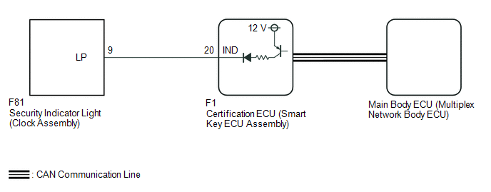
The certification ECU (smart key ECU assembly) blinks the security indicator light (clock assembly) when the immobiliser is set (engine switch off).
WIRING DIAGRAM
CAUTION / NOTICE / HINT
NOTICE:
- When using the Techstream with the engine switch off, connect the Techstream to the DLC3 and turn a courtesy light switch on and off at intervals of 1.5 seconds or less until communication between the Techstream and the vehicle begins. Then select the vehicle type under manual mode and enter the following menus: Body Electrical / Smart Key. While using the Techstream, periodically turn a courtesy light switch on and off at intervals of 1.5 seconds or less to maintain communication between the Techstream and the vehicle.
- Before replacing the certification ECU (smart key ECU assembly), refer
to Registration.
Click here
.gif)
PROCEDURE
|
1. |
CHECK FOR DTC |
(a) Check for DTCs.
Click here
OK:
DTCs are not output.
| NG | .gif) |
GO TO DIAGNOSTIC TROUBLE CODE CHART |
|
.gif)
|
2. |
PERFORM ACTIVE TEST USING TECHSTREAM (IMMOBILISER INDICATOR) |
(a) Connect the Techstream to the DLC3.
(b) Turn the engine switch on (IG).
(c) Turn the Techstream on.
(d) Enter the following menus: Body Electrical / Smart Key / Active Test.
(e) Perform the Active Test according to the display on the Techstream.
Body Electrical > Smart Key > Active Test|
Tester Display |
Measurement Item |
Type |
Diagnostic Note |
|---|---|---|---|
|
Immobiliser Indicator |
Security indicator light |
OFF/ON |
- |
|
Tester Display |
|---|
|
Immobiliser Indicator |
OK:
The security indicator light (clock assembly) operates normally.
| NG | |
GO TO STEP 4 |
|
|
3. |
CHECK SECURITY INDICATOR LIGHT (CLOCK ASSEMBLY) |
(a) When the immobiliser is set, check that the security indicator light (clock assembly) blinks.*1
OK:
The security indicator light (clock assembly) blinks normally.
(b) When the theft deterrent system is in the arming preparation state, check that the security indicator light (clock assembly) illuminates.*2
OK:
The security indicator light (clock assembly) illuminates normally.
|
Result |
Proceed to |
|---|---|
|
*1 is NG (*2 is OK) |
A |
|
*2 is NG (*1 is OK) |
B |
| A | |
REPLACE CERTIFICATION ECU (SMART KEY ECU ASSEMBLY) |
| B | |
REPLACE MAIN BODY ECU (MULTIPLEX NETWORK BODY ECU) |
|
4. |
CHECK HARNESS AND CONNECTOR (CERTIFICATION ECU (SMART KEY ECU ASSEMBLY) - SECURITY INDICATOR LIGHT (CLOCK ASSEMBLY)) |
(a) Disconnect the F1 certification ECU (smart key ECU assembly) connector.
(b) Disconnect the F81 security indicator light (clock assembly) connector.
(c) Measure the resistance according to the value(s) in the table below.
Standard Resistance:
|
Tester Connection |
Condition |
Specified Condition |
|---|---|---|
|
F1-20 (IND) - F81-9 (LP) |
Always |
Below 1 Ω |
|
F1-20 (IND) or F81-9 (LP) - Body ground |
Always |
10 kΩ or higher |
| NG | |
REPAIR OR REPLACE HARNESS OR CONNECTOR |
|
|
5. |
CHECK CERTIFICATION ECU (SMART KEY ECU ASSEMBLY) |
(a) Reconnect the F1 certification ECU (smart key ECU assembly) connector.
(b) Reconnect the F81 security indicator light (clock assembly) connector.
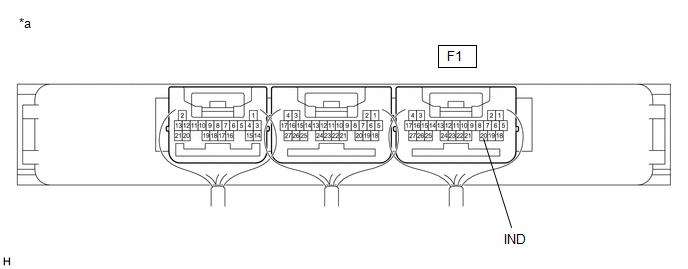
(c) Using an oscilloscope, check the waveform.
|
*a |
Component with harness connected (Certification ECU (Smart Key ECU Assembly)) |
- |
- |
Measurement Condition:
|
Tester Connection |
Switch Condition |
Specified Condition |
|---|---|---|
|
F1-20 (IND) - Body ground |
Engine switch off → on (IG) |
Pulse generation → Below 2 V |
| OK | |
REPLACE SECURITY INDICATOR LIGHT (CLOCK ASSEMBLY)
|
| NG | |
REPLACE CERTIFICATION ECU (SMART KEY ECU ASSEMBLY) |
 Immobiliser System does not Operate Properly
DESCRIPTION
The immobiliser system compares the ID code that is registered to the certification
ECU (smart key ECU assembly) with the ID code of the transponder chip that is embedded
in the elect ...

Other materials:
Toyota CH-R Service Manual > Continuously Variable Transaxle System: Acceleration Sensor Malfunction (P1586)
DESCRIPTION
The ECM determines the vehicle inclination based on a signal from the airbag
sensor assembly (yaw rate and acceleration sensor). If a malfunction of the airbag
sensor assembly (yaw rate and acceleration sensor) is determined based on a malfunction
signal from the skid control ECU ...
Toyota CH-R Service Manual > Blind Spot Monitor System: Power Source Circuit
DESCRIPTION
This circuit provides power to operate the blind spot monitor sensor.
WIRING DIAGRAM
CAUTION / NOTICE / HINT
NOTICE:
Inspect the fuses for circuits related to this system before performing the following
procedure.
PROCEDURE
1.
CHECK HARNESS AND CONNECTOR ...
Toyota C-HR (AX20) 2023-2026 Owner's Manual
Toyota CH-R Owners Manual
- For safety and security
- Instrument cluster
- Operation of each component
- Driving
- Interior features
- Maintenance and care
- When trouble arises
- Vehicle specifications
- For owners
Toyota CH-R Service Manual
- Introduction
- Maintenance
- Audio / Video
- Cellular Communication
- Navigation / Multi Info Display
- Park Assist / Monitoring
- Brake (front)
- Brake (rear)
- Brake Control / Dynamic Control Systems
- Brake System (other)
- Parking Brake
- Axle And Differential
- Drive Shaft / Propeller Shaft
- K114 Cvt
- 3zr-fae Battery / Charging
- Networking
- Power Distribution
- Power Assist Systems
- Steering Column
- Steering Gear / Linkage
- Alignment / Handling Diagnosis
- Front Suspension
- Rear Suspension
- Tire / Wheel
- Tire Pressure Monitoring
- Door / Hatch
- Exterior Panels / Trim
- Horn
- Lighting (ext)
- Mirror (ext)
- Window / Glass
- Wiper / Washer
- Door Lock
- Heating / Air Conditioning
- Interior Panels / Trim
- Lighting (int)
- Meter / Gauge / Display
- Mirror (int)
- Power Outlets (int)
- Pre-collision
- Seat
- Seat Belt
- Supplemental Restraint Systems
- Theft Deterrent / Keyless Entry

0.0088