Toyota CH-R Service Manual: Terminals Of Ecu
TERMINALS OF ECU
CHECK ENGINE SWITCH

(a) Measure the voltage and resistance according to the value(s) in the table below.
|
Terminal No. (Symbol) |
Input/Output |
Wiring Color |
Terminal Description |
Condition |
Specified Condition |
Related Data List Item/DTC |
|---|---|---|---|---|---|---|
|
F59-6 (AGND) - Body ground |
- |
P - Body ground |
Transponder key amplifier ground |
Always |
Below 1 Ω |
- |
|
F59-7 (TXCT) - F59-6 (AGND) |
Input |
B - P |
Immobiliser communication input |
Engine switch off, brake pedal not depressed, 30 seconds or more after driver door opened and then closed |
Below 1 V |
- |
|
F59-8 (CODE) - F59-6 (AGND) |
Output |
L - P |
Immobiliser communication output |
Engine switch off, brake pedal not depressed, 30 seconds or more after driver door opened and then closed |
Below 1 V |
- |
|
F59-10 (VC5) - F59-6 (AGND) |
Input |
Y - P |
Transponder key amplifier power supply |
Engine switch off, brake pedal not depressed, 30 seconds or more after driver door opened and then closed |
Below 1 V |
- |
(b) Check for pulses according to the value(s) in the table below.
|
Terminal No. (Symbol) |
Input/Output |
Wiring Color |
Terminal Description |
Condition |
Specified Condition |
Related Data List Item/DTC |
|---|---|---|---|---|---|---|
|
F59-7 (TXCT) - F59-6 (AGND) |
Input |
B - P |
Signal input from certification ECU (smart key ECU assembly) (Code sent from certification ECU (smart key ECU assembly) to transponder key amplifier built into engine switch, and then transmitted by transponder key amplifier antenna as radio waves) |
Engine switch off, electrical key transmitter sub-assembly not in cabin, within 30 seconds of engine switch pressed |
Pulse generation (See waveform 1) |
|
|
F59-8 (CODE) - F59-6 (AGND) |
Output |
L - P |
Signal output to certification ECU (smart key ECU assembly) (Radio waves from transponder key amplifier built into engine switch used to detect key information. Key information then sent to certification ECU (smart key ECU assembly)) |
Engine switch off, engine switch pressed with electrical key transmitter sub-assembly held near engine switch* |
Pulse generation (See waveform 2) |
|
|
F59-10 (VC5) - F59-6 (AGND) |
Input |
Y - P |
Transponder key amplifier power supply (Power supplied from certification ECU (smart key ECU assembly) when transponder key amplifier built into engine switch activated) |
Engine switch off, electrical key transmitter sub-assembly not in cabin, within 30 seconds of engine switch pressed |
Pulse generation (See waveform 3) |
HINT:
*: Remove the transmitter battery before performing this inspection.
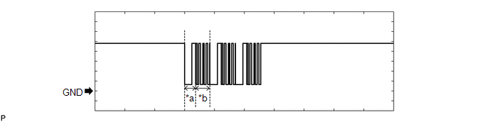
(c) Using an oscilloscope, check the waveform.
NOTICE:
The waveform shown in the illustration is an example for reference only. Noise, chattering, etc. are not shown.
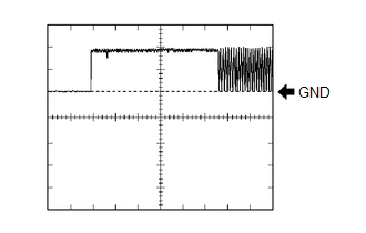
(1) Waveform 1 (Reference)
 Measurement Condition
|
Item |
Content |
|---|---|
|
Tester Connection |
F59-7 (TXCT) - F59-6 (AGND) |
|
Tool Setting |
2 V/DIV., 20 ms./DIV. |
|
Condition |
Engine switch off, electrical key transmitter sub-assembly not in cabin, within 30 seconds of engine switch pressed |
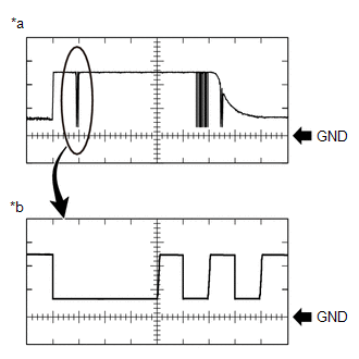
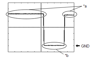
(2) Waveform 2 (Reference)
|
*a |
Waveform |
|
*b |
Waveform (detail) |
|
Item |
Content |
|---|---|
|
Tester Connection |
F59-8 (CODE) - F59-6 (AGND) |
|
Tool Setting |
|
|
Condition |
Engine switch off, engine switch pressed with electrical key transmitter sub-assembly held near engine switch* |
HINT:
*: Remove the transmitter battery before performing this inspection.
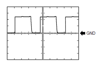
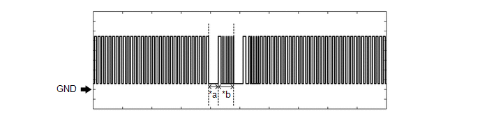
(3) Waveform 3 (Reference)
 Measurement Condition
|
Item |
Content |
|---|---|
|
Tester Connection |
F59-10 (VC5) - F59-6 (AGND) |
|
Tool Setting |
2 V/DIV., 200 ms./DIV. |
|
Condition |
Engine switch off, electrical key transmitter sub-assembly not in cabin, within 30 seconds of engine switch pressed |
CHECK CERTIFICATION ECU (SMART KEY ECU ASSEMBLY)
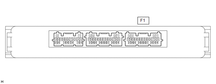
(a) Disconnect the F1 certification ECU (smart key ECU assembly) connector.
(b) Measure the voltage and resistance according to the value(s) in the table below.
|
Terminal No. (Symbol) |
Input/Output |
Wiring Color |
Terminal Description |
Condition |
Specified Condition |
Related Data List Item/DTC |
|---|---|---|---|---|---|---|
|
F1-4 (+B) - F1-18 (E) |
Input |
L - W-B |
+B power supply |
Always |
11 to 14 V |
- |
|
F1-18 (E) - Body ground |
- |
W-B - Body ground |
Ground |
Always |
Below 1 Ω |
- |
(c) Reconnect the F1 certification ECU (smart key ECU assembly) connector.
(d) Measure the voltage and resistance, and check for pulses according to the value(s) in the table below.
|
Terminal No. (Symbol) |
Input/Output |
Wiring Color |
Terminal Description |
Condition |
Specified Condition |
Related Data List Item/DTC |
|---|---|---|---|---|---|---|
|
F1-17 (IG1D) - F1-18 (E) |
Output |
GR - W-B |
Ignition power supply |
Engine switch off |
Below 1 V |
- |
|
Engine switch on (IG) |
11 to 14 V |
- |
||||
|
F1-5 (TXCT) - F1-11 (AGND) |
Output |
B - P |
Signal output to transponder key amplifier |
Engine switch off, brake pedal not depressed, 30 seconds or more after driver door opened and then closed |
Below 1 V |
|
|
F1-6 (CODE) - F1-11 (AGND) |
Input |
L - P |
Signal input from transponder key amplifier |
Engine switch off, brake pedal not depressed, 30 seconds or more after driver door opened and then closed |
Below 1 V |
|
|
F1-7 (VC5) - F1-11 (AGND) |
Output |
Y - P |
Transponder key amplifier power supply |
Engine switch off, brake pedal not depressed, 30 seconds or more after driver door opened and then closed |
Below 1 V |
|
|
F1-11 (AGND) - Body ground |
- |
P - Body ground |
Transponder key amplifier ground |
Always |
Below 1 Ω |
|
|
F1-20 (IND) - F1-18 (E) |
Output |
P - W-B |
Security indicator output |
Engine switch off → on (IG) |
Pulse generation → Below 2 V |
- |
(e) Check for pulses according to the value(s) in the table below.
|
Terminal No. (Symbol) |
Input/Output |
Wiring Color |
Terminal Description |
Condition |
Specified Condition |
Related Data List Item/DTC |
|---|---|---|---|---|---|---|
|
F1-5 (TXCT) - F1-11 (AGND) |
Output |
B - P |
Signal output to transponder key amplifier (Code sent from certification ECU (smart key ECU assembly) to transponder key amplifier built into engine switch, and then transmitted by transponder key amplifier antenna as radio waves) |
Engine switch off, electrical key transmitter sub-assembly not in cabin, within 30 seconds of engine switch pressed |
Pulse generation (See waveform 1) |
|
|
F1-6 (CODE) - F1-11 (AGND) |
Input |
L - P |
Signal input from transponder key amplifier (Radio waves from transponder key amplifier built into engine switch used to detect key information. Key information then sent to certification ECU (smart key ECU assembly)) |
Engine switch off, engine switch pressed with electrical key transmitter sub-assembly held near engine switch HINT: Remove the transmitter battery before performing this inspection. |
Pulse generation (See waveform 2) |
|
|
F1-7 (VC5) - F1-11 (AGND) |
Output |
Y - P |
Transponder key amplifier power supply (Power supplied from certification ECU (smart key ECU assembly) when transponder key amplifier built into engine switch activated) |
Engine switch off, electrical key transmitter sub-assembly not in cabin, within 30 seconds of engine switch pressed |
Pulse generation (See waveform 3) |
(f) Using an oscilloscope, check the waveform.
NOTICE:
The waveform shown in the illustration is an example for reference only. Noise, chattering, etc. are not shown.
(1) Waveform 1 (Reference)
 Measurement Condition
|
Item |
Content |
|---|---|
|
Tester Connection |
F1-5 (TXCT) - F1-11 (AGND) |
|
Tool Setting |
2 V/DIV., 20 ms./DIV. |
|
Condition |
Engine switch off, electrical key transmitter sub-assembly not in cabin, within 30 seconds of engine switch pressed |
(2) Waveform 2 (Reference)
|
*a |
Waveform |
|
*b |
Waveform (detail) |
|
Item |
Content |
|---|---|
|
Tester Connection |
F1-6 (CODE) - F1-11 (AGND) |
|
Tool Setting |
|
|
Condition |
Engine switch off, engine switch pressed with electrical key transmitter sub-assembly held near engine switch* |
HINT:
*: Remove the transmitter battery before performing this inspection.
(3) Waveform 3 (Reference)
 Measurement Condition
|
Item |
Content |
|---|---|
|
Tester Connection |
F1-7 (VC5) - F1-11 (AGND) |
|
Tool Setting |
2 V/DIV., 200 ms./DIV. |
|
Condition |
Engine switch off, electrical key transmitter sub-assembly not in cabin, within 30 seconds of engine switch pressed |
CHECK ID CODE BOX (IMMOBILISER CODE ECU)

(a) Disconnect the F21 ID code box (immobiliser code ECU) connector.
(b) Measure the voltage and resistance according to the value(s) in the table below.
|
Terminal No. (Symbol) |
Input/Output |
Wiring Color |
Terminal Description |
Condition |
Specified Condition |
Related Data List Item/DTC |
|---|---|---|---|---|---|---|
|
F21-1 (+B) - Body ground |
Input |
W - Body ground |
+B power supply |
Always |
11 to 14 V |
B2789 |
|
F21-5 (GND) - Body ground |
- |
W-B - Body ground |
Ground |
Always |
Below 1 Ω |
B2789 |
(c) Reconnect the F21 ID code box (immobiliser code ECU) connector.
(d) Measure the voltage and check for pulses according to the value(s) in the table below.
|
Terminal No. (Symbol) |
Input/Output |
Wiring Color |
Terminal Description |
Condition |
Specified Condition |
Related Data List Item/DTC |
|---|---|---|---|---|---|---|
|
F21-3 (EFII) - F21-5 (GND) |
Input |
G - W-B |
EFI communication input (Signal input from ECM to ID code box (immobiliser code ECU)) |
Engine switch off |
11 to 14 V |
|
|
F21-4 (EFIO) - F21-5 (GND) |
Output |
R - W-B |
EFI communication output (Signal output from ID code box (immobiliser code ECU) to ECM) |
Engine switch off |
11 to 14 V → Below 1 V |
|
|
F21-3 (EFII) - F21-5 (GND) |
Input |
G - W-B |
EFI communication input (Signal input from ECM to ID code box (immobiliser code ECU)) |
Within 3 seconds of engine start or within 3 seconds of engine switch turned on (IG) after cable disconnected and reconnected to battery |
Pulse generation (See waveform 1) |
|
|
F21-4 (EFIO) - F21-5 (GND) |
Output |
R - W-B |
EFI communication output (Signal output from ID code box (immobiliser code ECU) to ECM) |
Engine switch turned on (IG) using registered electrical key transmitter sub-assembly |
Pulse generation (See waveform 2) |
(e) Using an oscilloscope, check the waveform.
NOTICE:
The waveform shown in the illustration is an example for reference only. Noise, chattering, etc. are not shown.
(1) Waveform 1 (Reference)
|
*a |
Approximately 160 ms. |
*b |
Approximately 270 ms. |
|
Item |
Content |
|---|---|
|
Tester Connection |
F21-3 (EFII) - F21-5 (GND) |
|
Tool Setting |
2 V/DIV., 500 ms./DIV. |
|
Condition |
Within 3 seconds of engine start or within 3 seconds of engine switch turned on (IG) after cable disconnected and reconnected to battery |
(2) Waveform 2 (Reference)
|
*a |
Approximately 160 ms. |
*b |
Approximately 270 ms. |
|
Item |
Content |
|---|---|
|
Tester Connection |
F21-4 (EFIO) - F21-5 (GND) |
|
Tool Setting |
2 V/DIV., 500 ms./DIV. |
|
Condition |
Engine switch turned on (IG) using registered electrical key transmitter sub-assembly |
CHECK STEERING LOCK ECU (STEERING LOCK ACTUATOR OR UPPER BRACKET ASSEMBLY)

(a) Measure the voltage and resistance, and check for pulses according to the value(s) in the table below.
|
Terminal No. (Symbol) |
Input/Output |
Wiring Color |
Terminal Description |
Condition |
Specified Condition |
Related Data List Item/DTC |
|---|---|---|---|---|---|---|
|
F78-1 (GND) - Body ground |
- |
W-B - Body ground |
Ground |
Always |
Below 1 Ω |
- |
|
F78-3 (IGE) - F78-1 (GND) |
Input |
P - W-B |
Steering lock motor operation permission signal (motor operation permission signal supplied by certification ECU (smart key ECU assembly)) |
Steering lock motor operating when all conditions met, and then door opened:
|
Pulse generation (See waveform 1) |
|
|
F78-4 (SLP1) - F78-1 (GND) |
Output |
G - W-B |
Steering lock bar position signal (signal output from steering unlock sensor) |
Steering locked → unlocked* |
11 to 14 V → Below 1.5 V |
Sensor Value |
|
F78-6 (IG2) - F78-1 (GND) |
Input |
B - W-B |
IG signal (IG2 power supply input for steering lock motor) |
Engine switch off |
Below 1 V |
B2788 |
|
Engine switch on (IG) |
11 to 14 V |
|||||
|
F78-7 (B) - Body ground |
Input |
L - Body ground |
Constant power supply |
Always |
11 to 14 V |
B2788 |
HINT:
*: The steering locks when any door is opened with the shift lever in P and the engine switch off. The steering unlocks when the engine switch is turned on (ACC).
(b) Using an oscilloscope, check the waveform.
NOTICE:
The waveform shown in the illustration is an example for reference only. Noise, chattering, etc. are not shown.
(1) Waveform 1 (Reference)
|
*a |
Steering lock motor not operating |
|
*b |
Steering lock motor operating |
|
Item |
Content |
|---|---|
|
Tester Connection |
|
|
Tool Setting |
2 V/DIV., 200 ms./DIV. |
|
Condition |
Steering lock motor operating when all conditions met, and then door opened:
|
CHECK ECM
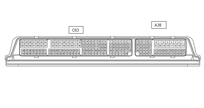
(a) Measure the voltage and resistance, and check for pulses according to the value(s) in the table below.
|
Terminal No. (Symbol) |
Input/Output |
Wiring Color |
Terminal Description |
Condition |
Specified Condition |
Related Data List Item/DTC |
|---|---|---|---|---|---|---|
|
C63-59 (E1) - Body ground |
- |
W-B - Body ground |
Ground |
Always |
Below 1 Ω |
- |
|
A38-45 (IMO) - C63-59 (E1) |
Output |
GR - W-B |
ID code box (immobiliser code ECU) communication output |
Engine switch off |
11 to 14 V |
- |
|
A38-45 (IMO) - C63-59 (E1) |
Output |
GR - W-B |
ID code box (immobiliser code ECU) communication output |
Within 3 seconds of engine start or within 3 seconds of engine switch turned on (IG) after cable disconnected and reconnected to battery |
Pulse generation (See waveform 1) |
- |
|
A38-28 (IMI) - C63-59 (E1) |
Input |
BE - W-B |
ID code box (immobiliser code ECU) communication input |
Engine switch off |
11 to 14 V → Below 1 V |
- |
|
A38-28 (IMI) - C63-59 (E1) |
Input |
BE - W-B |
ID code box (immobiliser code ECU) communication input |
Engine switch turned on (IG) using registered electrical key transmitter sub-assembly |
Pulse generation (See waveform 2) |
- |
(b) Using an oscilloscope, check the waveform.
NOTICE:
The waveform shown in the illustration is an example for reference only. Noise, chattering, etc. are not shown.
(1) Waveform 1 (Reference)
|
*a |
Approximately 160 ms. |
*b |
Approximately 270 ms. |
|
Item |
Content |
|---|---|
|
Tester Connection |
A38-45 (IMO) - C63-59 (E1) |
|
Tool Setting |
2 V/DIV., 500 ms./DIV. |
|
Condition |
Within 3 seconds of engine start or within 3 seconds of engine switch turned on (IG) after cable disconnected and reconnected to battery |
(2) Waveform 2 (Reference)
|
*a |
Approximately 160 ms. |
*b |
Approximately 270 ms. |
|
Item |
Content |
|---|---|
|
Tester Connection |
A38-28 (IMI) - C63-59 (E1) |
|
Tool Setting |
2 V/DIV., 500 ms./DIV. |
|
Condition |
Engine switch turned on (IG) using registered electrical key transmitter sub-assembly |
 Registration
REGISTRATION
PROCEDURE
1. CAUTION REGARDING INTERFERENCE WITH ELECTRONIC DEVICES
CAUTION:
People with implantable cardiac pacemakers, cardiac resynchronization
therapy-pacemakers or im ...
 Diagnosis System
DIAGNOSIS SYSTEM
DESCRIPTION
(a) The certification ECU (smart key ECU assembly) and ECM control the vehicle
immobiliser system functions. Immobiliser system data and Diagnostic Trouble Codes
(DT ...
Other materials:
Toyota CH-R Service Manual > Front Wiper Motor: Components
COMPONENTS
ILLUSTRATION
*1
WINDSHIELD OUTSIDE MOULDING LH
*2
WINDSHIELD OUTSIDE MOULDING RH
ILLUSTRATION
*A
for USA and Canada
*B
except USA and Canada
*1
COWL TOP VEN ...
Toyota CH-R Service Manual > Back Door Lock: Removal
REMOVAL
PROCEDURE
1. REMOVE PACKAGE TRAY TRIM PANEL ASSEMBLY (w/ Package Tray Trim)
Click here
2. REMOVE TONNEAU COVER ASSEMBLY (w/ Tonneau Cover)
Click here
3. REMOVE BACK DOOR TRIM UPPER PANEL ASSEMBLY
Click here
4. REMOVE BACK DOOR SIDE GARNISH LH
Click here
5. R ...
Toyota C-HR (AX20) 2023-2026 Owner's Manual
Toyota CH-R Owners Manual
- For safety and security
- Instrument cluster
- Operation of each component
- Driving
- Interior features
- Maintenance and care
- When trouble arises
- Vehicle specifications
- For owners
Toyota CH-R Service Manual
- Introduction
- Maintenance
- Audio / Video
- Cellular Communication
- Navigation / Multi Info Display
- Park Assist / Monitoring
- Brake (front)
- Brake (rear)
- Brake Control / Dynamic Control Systems
- Brake System (other)
- Parking Brake
- Axle And Differential
- Drive Shaft / Propeller Shaft
- K114 Cvt
- 3zr-fae Battery / Charging
- Networking
- Power Distribution
- Power Assist Systems
- Steering Column
- Steering Gear / Linkage
- Alignment / Handling Diagnosis
- Front Suspension
- Rear Suspension
- Tire / Wheel
- Tire Pressure Monitoring
- Door / Hatch
- Exterior Panels / Trim
- Horn
- Lighting (ext)
- Mirror (ext)
- Window / Glass
- Wiper / Washer
- Door Lock
- Heating / Air Conditioning
- Interior Panels / Trim
- Lighting (int)
- Meter / Gauge / Display
- Mirror (int)
- Power Outlets (int)
- Pre-collision
- Seat
- Seat Belt
- Supplemental Restraint Systems
- Theft Deterrent / Keyless Entry

0.0097