Toyota CH-R Service Manual: Parts Location
PARTS LOCATION
ILLUSTRATION
|
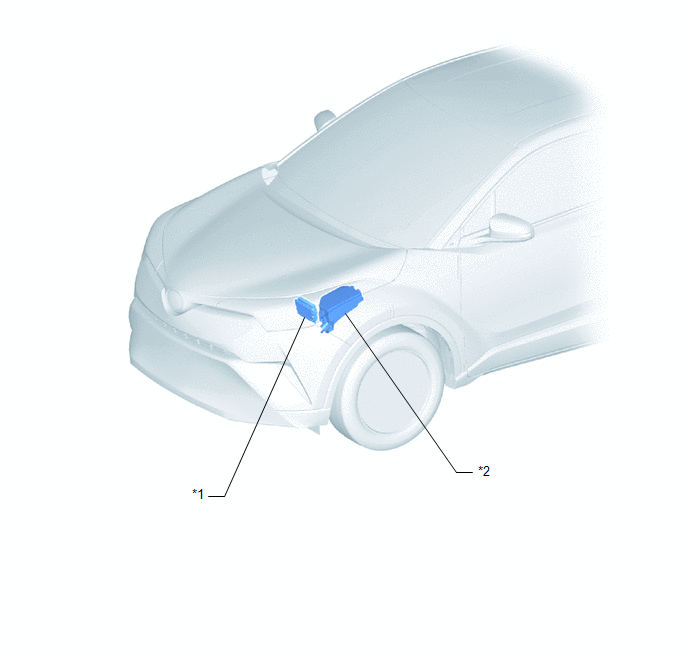
*1 |
ECM |
*2 |
NO. 1 ENGINE ROOM RELAY BLOCK |
ILLUSTRATION
|
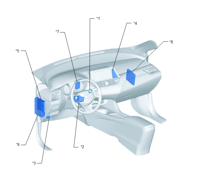
*1 |
ENGINE SWITCH |
*2 |
STEERING LOCK ECU (STEERING LOCK ACTUATOR OR UPPER BRACKET ASSEMBLY) |
|
*3 |
DLC3 |
*4 |
CLOCK ASSEMBLY - SECURITY INDICATOR LIGHT |
|
*5 |
MAIN BODY ECU (MULTIPLEX NETWORK BODY ECU) |
*6 |
INSTRUMENT PANEL JUNCTION BLOCK ASSEMBLY - AM2 FUSE - ECU-IG2 NO. 3 FUSE - STRG LOCK FUSE - ECU-B NO. 1 FUSE |
|
*7 |
ID CODE BOX (IMMOBILISER CODE ECU) |
*8 |
CERTIFICATION ECU (SMART KEY ECU ASSEMBLY) |
 Precaution
PRECAUTION
PRECAUTIONS WHEN USING TECHSTREAM
(a) When using the Techstream with the engine switch off, connect the Techstream
to the DLC3 and turn a courtesy light switch on and off at intervals o ...
 System Description
SYSTEM DESCRIPTION
IMMOBILISER SYSTEM DESCRIPTION
(a) The immobiliser system determines whether or not to enable starting of the
SFI system based on a comparison of the key ID code and the code re ...
Other materials:
Toyota CH-R Service Manual > Vehicle Stability Control System: Open in ABS Solenoid Relay Circuit (C146E)
DESCRIPTION
The ABS solenoid relay is built into the skid control ECU in the brake actuator
assembly. The ABS solenoid relay supplies power to the ABS and TRAC solenoids. The
skid control ECU detects a solenoid relay malfunction by performing a self check
and relay operation check.
...
Toyota CH-R Service Manual > Seat Heater System: How To Proceed With Troubleshooting
CAUTION / NOTICE / HINT
HINT:
Use the following procedure to troubleshoot the seat heater system.
*: Use the Techstream.
PROCEDURE
1.
VEHICLE BROUGHT TO WORKSHOP
NEXT
...
Toyota C-HR (AX20) 2023-2026 Owner's Manual
Toyota CH-R Owners Manual
- For safety and security
- Instrument cluster
- Operation of each component
- Driving
- Interior features
- Maintenance and care
- When trouble arises
- Vehicle specifications
- For owners
Toyota CH-R Service Manual
- Introduction
- Maintenance
- Audio / Video
- Cellular Communication
- Navigation / Multi Info Display
- Park Assist / Monitoring
- Brake (front)
- Brake (rear)
- Brake Control / Dynamic Control Systems
- Brake System (other)
- Parking Brake
- Axle And Differential
- Drive Shaft / Propeller Shaft
- K114 Cvt
- 3zr-fae Battery / Charging
- Networking
- Power Distribution
- Power Assist Systems
- Steering Column
- Steering Gear / Linkage
- Alignment / Handling Diagnosis
- Front Suspension
- Rear Suspension
- Tire / Wheel
- Tire Pressure Monitoring
- Door / Hatch
- Exterior Panels / Trim
- Horn
- Lighting (ext)
- Mirror (ext)
- Window / Glass
- Wiper / Washer
- Door Lock
- Heating / Air Conditioning
- Interior Panels / Trim
- Lighting (int)
- Meter / Gauge / Display
- Mirror (int)
- Power Outlets (int)
- Pre-collision
- Seat
- Seat Belt
- Supplemental Restraint Systems
- Theft Deterrent / Keyless Entry

0.0107