Toyota CH-R Service Manual: Meter Illumination does not Dim at Night
DESCRIPTION
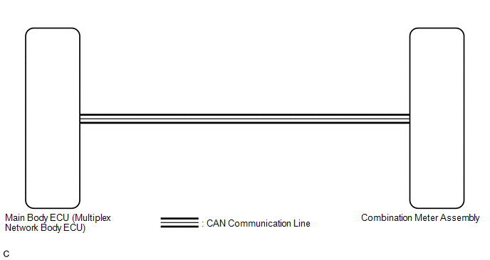
In this circuit, the combination meter assembly receives auto dimmer signals from the main body ECU (multiplex network body ECU) via CAN communication. When the combination meter assembly receives an auto dimmer signal, it dims the meter illumination (warning and indicator lights).
The main body ECU (multiplex network body ECU) determines whether it is daytime or nighttime based on the waveform transmitted from the automatic light control sensor. If the main body ECU (multiplex network body ECU) determines that it is nighttime and the headlight dimmer switch assembly is in the tail, head, or AUTO position, the ECU sends an auto dimmer signal to the combination meter assembly.
According to this signal, the combination meter assembly dims the meter illumination.
HINT:
When the meter illumination does not dim at night, there may be a malfunction in the automatic light control sensor, main body ECU (multiplex network body ECU), CAN communication system, wire harness, connector, or combination meter assembly.
WIRING DIAGRAM
CAUTION / NOTICE / HINT
NOTICE:
- Before replacing the main body ECU (multiplex network body ECU), refer
to Registration.*1
Click here
.gif)
- When replacing the combination meter assembly, always replace it with
a new one. If a combination meter assembly which was installed to another
vehicle is used, the information stored in it will not match the information
from the vehicle and a DTC may be stored.
- *1: w/ Smart Key System
HINT:
- The automatic light control sensor sensitivity can be customized.
Click here
- Setting the meter illumination level to maximum brightness prevents the meter illumination from dimming when the headlight dimmer switch assembly is changed to the tail, head, or AUTO position at night. Therefore, check the meter illumination setting before proceeding to the following steps.
PROCEDURE
|
1. |
CHECK CAN COMMUNICATION SYSTEM |
(a) Check if CAN communication DTCs are output.
Click here
|
Result |
Proceed to |
|---|---|
|
CAN communication DTCs are not output. |
A |
|
CAN communication DTCs are output. |
B |
| B | .gif) |
GO TO CAN COMMUNICATION SYSTEM |
|
.gif)
|
2. |
CHECK FOR DTC |
(a) Check if lighting system DTCs are output.
Click here
|
Result |
Proceed to |
|---|---|
|
DTC B1244 is not output. |
A |
|
DTC B1244 is output. |
B |
| B | |
GO TO DTC B1244 |
|
|
3. |
REPLACE COMBINATION METER ASSEMBLY |
(a) Replace the combination meter assembly with a new one.
Click here
OK:
The operation of the combination meter assembly returns to normal.
| OK | |
END |
| NG | |
REPLACE MAIN BODY ECU (MULTIPLEX NETWORK BODY ECU)
|
 Operating Light Control Rheostat does not Change Light Brightness
DESCRIPTION
The illumination intensity of the combination meter is increased by turning the
knob of the light control rheostat upward, and decreased by turning the knob downward.
WIRING DIAGRAM
...
 Meter Illumination is Always Dark
DESCRIPTION
The combination meter assembly receives signals from this circuit to adjust the
illumination of the combination meter assembly. The combination meter assembly sets
the illumination le ...
Other materials:
Toyota CH-R Owners Manual > Child restraint systems: Child restraint system fixed with a child restraint LATCH anchor
■ Child restraint LATCH anchors LATCH anchors are provided for
the rear outboard seats.
(Buttons displaying the location of the anchors are attached to the seats.)
■ When installing in the rear outboard seats Install the child
restraint system in accordance to the operation manual encl ...
Toyota CH-R Service Manual > Shift Lever: Disassembly
DISASSEMBLY
PROCEDURE
1. REMOVE SHIFTING HOLE COVER SUB-ASSEMBLY
(a) Disengage the 4 guides and 6 claws to remove the shifting hole cover
sub-assembly from the upper console panel sub-assembly.
2. REMOVE SHIFT POSITION INDICATOR
...
Toyota C-HR (AX20) 2023-2026 Owner's Manual
Toyota CH-R Owners Manual
- For safety and security
- Instrument cluster
- Operation of each component
- Driving
- Interior features
- Maintenance and care
- When trouble arises
- Vehicle specifications
- For owners
Toyota CH-R Service Manual
- Introduction
- Maintenance
- Audio / Video
- Cellular Communication
- Navigation / Multi Info Display
- Park Assist / Monitoring
- Brake (front)
- Brake (rear)
- Brake Control / Dynamic Control Systems
- Brake System (other)
- Parking Brake
- Axle And Differential
- Drive Shaft / Propeller Shaft
- K114 Cvt
- 3zr-fae Battery / Charging
- Networking
- Power Distribution
- Power Assist Systems
- Steering Column
- Steering Gear / Linkage
- Alignment / Handling Diagnosis
- Front Suspension
- Rear Suspension
- Tire / Wheel
- Tire Pressure Monitoring
- Door / Hatch
- Exterior Panels / Trim
- Horn
- Lighting (ext)
- Mirror (ext)
- Window / Glass
- Wiper / Washer
- Door Lock
- Heating / Air Conditioning
- Interior Panels / Trim
- Lighting (int)
- Meter / Gauge / Display
- Mirror (int)
- Power Outlets (int)
- Pre-collision
- Seat
- Seat Belt
- Supplemental Restraint Systems
- Theft Deterrent / Keyless Entry

0.0096