Toyota CH-R Service Manual: Removal
REMOVAL
CAUTION / NOTICE / HINT
The necessary procedures (adjustment, calibration, initialization, or registration) that must be performed after parts are removed, installed, or replaced during the ID code box (immobiliser code ECU) removal/installation are shown below.
Necessary Procedure After Parts Removed/Installed/Replaced|
Replacement Part or Procedure |
Necessary Procedures |
Effects / Inoperative when not performed |
Link |
|---|---|---|---|
|
Disconnect cable from negative battery terminal |
Initialize back door lock |
Power door lock control system |
|
|
Memorize steering angle neutral point |
Lane departure alert system (w/ Steering Control) |
|
|
|
Pre-collision system |
|||
|
ID code box (immobiliser code ECU) |
Perform code registration (Immobiliser system) |
|
w/ Smart Key System: |
PROCEDURE
1. REMOVE AIR CONDITIONER UNIT ASSEMBLY (for Cold Area Specification Vehicles)
Click here .gif)
2. REMOVE AIR CONDITIONER UNIT ASSEMBLY (except Cold Area Specification Vehicles)
Click here
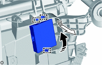
3. REMOVE ID CODE BOX (IMMOBILISER CODE ECU)
(a) Disengage the guides to remove the ID code box (immobiliser code ECU) as shown in the illustration.
.png) |
Remove in this Direction (1) |
.png) |
Remove in this Direction (2) |
 Components
COMPONENTS
ILLUSTRATION
*1
ID CODE BOX (IMMOBILISER CODE ECU)
-
-
...
 Installation
INSTALLATION
CAUTION / NOTICE / HINT
NOTICE:
Before replacing the ID code box (immobiliser code ECU), refer to Registration.
Click here
PROCEDURE
1. INSTALL ID CODE BOX (IMMOBILISER CODE ECU)
...
Other materials:
Toyota CH-R Service Manual > Lighting System: IG Signal Circuit
DESCRIPTION
This circuit detects the ignition switch ON or off condition, and sends it to
the main body ECU (multiplex network body ECU).
WIRING DIAGRAM
CAUTION / NOTICE / HINT
NOTICE:
Inspect the fuses for circuits related to this system before performing
the following procedur ...
Toyota CH-R Service Manual > Electric Parking Brake System: How To Proceed With Troubleshooting
CAUTION / NOTICE / HINT
HINT:
*: Use the Techstream.
PROCEDURE
1.
VEHICLE BROUGHT TO WORKSHOP
NEXT
2.
CUSTOMER PROBLEM ANALYSIS
(a) Interview the customer and confir ...
Toyota C-HR (AX20) 2023-2026 Owner's Manual
Toyota CH-R Owners Manual
- For safety and security
- Instrument cluster
- Operation of each component
- Driving
- Interior features
- Maintenance and care
- When trouble arises
- Vehicle specifications
- For owners
Toyota CH-R Service Manual
- Introduction
- Maintenance
- Audio / Video
- Cellular Communication
- Navigation / Multi Info Display
- Park Assist / Monitoring
- Brake (front)
- Brake (rear)
- Brake Control / Dynamic Control Systems
- Brake System (other)
- Parking Brake
- Axle And Differential
- Drive Shaft / Propeller Shaft
- K114 Cvt
- 3zr-fae Battery / Charging
- Networking
- Power Distribution
- Power Assist Systems
- Steering Column
- Steering Gear / Linkage
- Alignment / Handling Diagnosis
- Front Suspension
- Rear Suspension
- Tire / Wheel
- Tire Pressure Monitoring
- Door / Hatch
- Exterior Panels / Trim
- Horn
- Lighting (ext)
- Mirror (ext)
- Window / Glass
- Wiper / Washer
- Door Lock
- Heating / Air Conditioning
- Interior Panels / Trim
- Lighting (int)
- Meter / Gauge / Display
- Mirror (int)
- Power Outlets (int)
- Pre-collision
- Seat
- Seat Belt
- Supplemental Restraint Systems
- Theft Deterrent / Keyless Entry

0.0085