Toyota CH-R Service Manual: IG Signal Circuit
DESCRIPTION
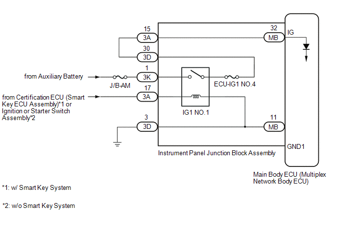
This circuit detects the ignition switch ON or off condition, and sends it to the main body ECU (multiplex network body ECU).
WIRING DIAGRAM
CAUTION / NOTICE / HINT
NOTICE:
- Inspect the fuses for circuits related to this system before performing the following procedure.
- Before replacing the main body ECU (multiplex network body ECU), refer
to Registration*1.
Click here
.gif)
- *1: w/ Smart Key System
PROCEDURE
|
1. |
CHECK FOR DTC (SMART KEY SYSTEM (for Start Function)) |
HINT:
If the vehicle is not equipped with an smart key system, proceed to next step (A).
(a) Clear the DTCs.
Click here
(b) Check for DTCs.
Click here
|
Result |
Proceed to |
|---|---|
|
Smart Key System (for Start Function) DTCs are not output |
A |
|
Smart Key System (for Start Function) DTCs are output |
B |
| B | .gif) |
GO TO SMART KEY SYSTEM (for Start Function) |
|
.gif)
|
2. |
READ VALUE USING TECHSTREAM |
(a) Connect the Techstream to the DLC3.
(b) Turn the ignition switch to ON.
(c) Turn the Techstream on.
(d) Enter the following menus: Body Electrical / Main Body / Data List.
(e) Read the Data List according to the display on the Techstream.
Body Electrical > Main Body > Data List|
Tester Display |
Measurement Item |
Range |
Normal Condition |
Diagnostic Note |
|---|---|---|---|---|
|
IG SW |
Ignition switch ON signal |
ON or OFF |
ON: Ignition switch on OFF: Ignition switch off |
- |
|
Tester Display |
|---|
|
IG SW |
OK:
Normal conditions listed above are displayed.
|
Result |
Proceed to |
|---|---|
|
OK |
A |
|
NG |
B |
| A | |
PROCEED TO NEXT SUSPECTED AREA SHOWN IN PROBLEM SYMPTOMS TABLE
|
|
|
3. |
CHECK HARNESS AND CONNECTOR (BATTERY POWER SOURCE - INSTRUMENT PANEL JUNCTION BLOCK ASSEMBLY) |
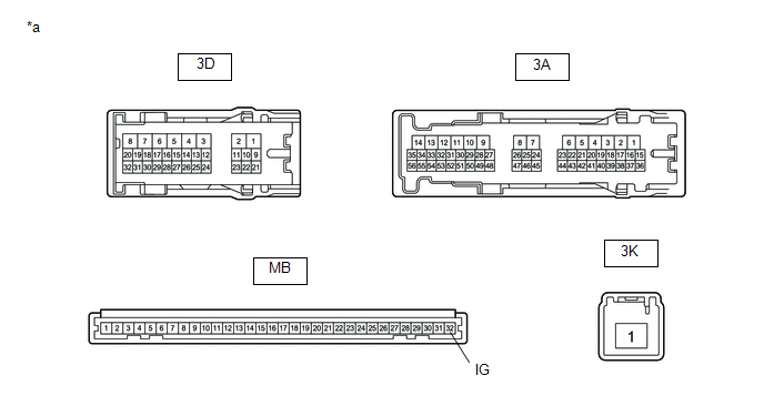
(a) Disconnect the 3K instrument panel junction block assembly connector.
(b) Measure the voltage according to the value(s) in the table below.
Standard Voltage:
|
Tester Connection |
Condition |
Specified Condition |
|---|---|---|
|
3K-1 - Body ground |
Always |
11 to 14 V |
| NG | |
REPAIR OR REPLACE HARNESS OR CONNECTOR |
|
|
4. |
CHECK HARNESS AND CONNECTOR (INSTRUMENT PANEL JUNCTION BLOCK ASSEMBLY - INSTRUMENT PANEL JUNCTION BLOCK ASSEMBLY) |
(a) Remove the instrument panel junction block assembly.
Click here
(b) Measure the voltage according to the value(s) in the table below.
Standard Resistance:
|
Tester Connection |
Switch Condition |
Specified Condition |
|---|---|---|
|
3D-30 - 3A-15 |
Ignition switch off |
Below 1 Ω |
|
3D-30 or 3A-15 - Body ground |
Ignition switch off |
10 kΩ or higher |
| NG | |
REPAIR OR REPLACE HARNESS OR CONNECTOR |
|
|
5. |
INSPECT INSTRUMENT PANEL JUNCTION BLOCK ASSEMBLY |
(a) Remove the instrument panel junction block assembly.
Click here
(b) Remove the main body ECU (multiplex network body ECU) from the instrument panel junction block assembly.
Click here
(c) Measure the resistance according to the value(s) in the table below.
|
*a |
Component without harness connected (Instrument Panel Junction Block Assembly) |
- |
- |
Standard Resistance:
|
Tester Connection |
Condition |
Specified Condition |
|---|---|---|
|
3K-1 - 3D-30 |
Battery not connected to 3A-17 and 3D-3 |
10 kΩ or higher |
|
3K-1 - 3D-30 |
Battery positive (+) → 3A-17 Battery negative (-) → 3D-3 |
Below 1 Ω |
|
3A-15 - MB-32 (IG) |
Always |
Below 1 Ω |
| OK | |
REPLACE MAIN BODY ECU (MULTIPLEX NETWORK BODY ECU)
|
| NG | |
REPLACE INSTRUMENT PANEL JUNCTION BLOCK ASSEMBLY
|
 Diagnosis System
DIAGNOSIS SYSTEM
DESCRIPTION
(a) Lighting system data can be read from the Data Link Connector 3 (DLC3) of
the vehicle. When the system seems to be malfunctioning, use the Techstream to check
fo ...
 ACC Signal Circuit
DESCRIPTION
This circuit detects the ignition switch ACC or off condition, and sends it to
the main body ECU (multiplex network body ECU).
WIRING DIAGRAM
CAUTION / NOTICE / HINT
NOTICE:
...
Other materials:
Toyota CH-R Service Manual > Door Lock: Door Control Relay
Components
COMPONENTS
ILLUSTRATION
*1
DOUBLE LOCK DOOR CONTROL RELAY ASSEMBLY
-
-
N*m (kgf*cm, ft.*lbf): Specified torque
-
-
Installation
INSTALLATION
PROCEDURE
1. INSTALL DOUBLE LOCK D ...
Toyota CH-R Service Manual > Vehicle Stability Control System: Open in Front Speed Sensor RH (C1330-C1467)
DESCRIPTION
Each speed sensor detects wheel speed and sends signals to the skid control ECU
(brake actuator assembly). These signals are used by the ABS.
HINT:
The output voltage values shown below are for when the vehicle wire harnesses
are connected to the skid control ECU (brake actuator a ...
Toyota C-HR (AX20) 2023-2026 Owner's Manual
Toyota CH-R Owners Manual
- For safety and security
- Instrument cluster
- Operation of each component
- Driving
- Interior features
- Maintenance and care
- When trouble arises
- Vehicle specifications
- For owners
Toyota CH-R Service Manual
- Introduction
- Maintenance
- Audio / Video
- Cellular Communication
- Navigation / Multi Info Display
- Park Assist / Monitoring
- Brake (front)
- Brake (rear)
- Brake Control / Dynamic Control Systems
- Brake System (other)
- Parking Brake
- Axle And Differential
- Drive Shaft / Propeller Shaft
- K114 Cvt
- 3zr-fae Battery / Charging
- Networking
- Power Distribution
- Power Assist Systems
- Steering Column
- Steering Gear / Linkage
- Alignment / Handling Diagnosis
- Front Suspension
- Rear Suspension
- Tire / Wheel
- Tire Pressure Monitoring
- Door / Hatch
- Exterior Panels / Trim
- Horn
- Lighting (ext)
- Mirror (ext)
- Window / Glass
- Wiper / Washer
- Door Lock
- Heating / Air Conditioning
- Interior Panels / Trim
- Lighting (int)
- Meter / Gauge / Display
- Mirror (int)
- Power Outlets (int)
- Pre-collision
- Seat
- Seat Belt
- Supplemental Restraint Systems
- Theft Deterrent / Keyless Entry

0.0128