Toyota CH-R Service Manual: Removal
REMOVAL
CAUTION / NOTICE / HINT
The necessary procedures (adjustment, calibration, initialization, or registration) that must be performed after parts are removed, installed, or replaced during the front seat cushion airbag assembly RH removal/installation are shown below.
Necessary Procedure After Parts Removed/Installed/Replaced|
Replacement Part or Procedure |
Necessary Procedures |
Effects / Inoperative when not performed |
Link |
|---|---|---|---|
|
Removal/installation of the front passenger seat |
Zero point calibration (Occupant classification system) |
|
|
|
Disconnect cable from negative battery terminal |
Memorize steering angle neutral point |
Lane departure alert system (w/ Steering Control) |
|
|
Pre-collision system |
|||
|
Initialize back door lock |
Power door lock control system |
|
.png)
- Be sure to read Precaution thoroughly before servicing.
Click here
.gif)
- Wear protective gloves. Sharp areas on the parts may injure your hands.
NOTICE:
If the front seat cushion airbag assembly RH has been deployed, replace the front seat cushion airbag assembly RH, front seat adjuster assembly RH, separate type front seat cushion pad and separate type front seat cushion cover with the necessary parts in accordance with the extent of the collision damage.
Click here
PROCEDURE
1. REMOVE SEPARATE TYPE FRONT SEAT CUSHION COVER WITH PAD
Click here
2. REMOVE FRONT SEAT CUSHION AIRBAG ASSEMBLY RH
CAUTION:
When storing the front seat cushion airbag assembly RH, keep the airbag deployment side facing upward.
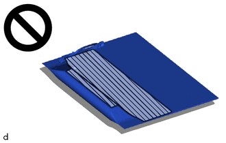
.png) |
Deployment Side |
|
(a) Disengage the clamps and claw. HINT: Disengage the clamps first. |
|
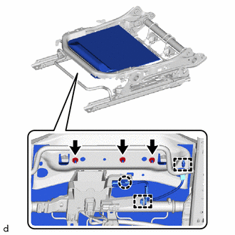
(b) Remove the 3 nuts.
NOTICE:
- Do not reuse the nuts.
- Make sure that the front seat adjuster assembly RH is not deformed. If it is deformed, replace it with a new one.
|
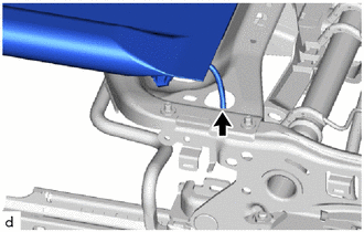
(c) Pass the airbag wire harness through the hole to remove the front seat cushion airbag assembly RH. |
|
 On-vehicle Inspection
ON-VEHICLE INSPECTION
CAUTION / NOTICE / HINT
CAUTION:
Be sure to correctly follow the removal and installation procedures for the front
seat cushion airbag assembly RH.
PROCEDURE
1. INSPECT FR ...
 Disposal
DISPOSAL
CAUTION / NOTICE / HINT
CAUTION:
Before performing pre-disposal deployment of any SRS part, review and closely
follow all applicable environmental and hazardous material regulations. Pre ...
Other materials:
Toyota CH-R Service Manual > Immobiliser System(w/ Smart Key System): Security Indicator Light Does not Blink
DESCRIPTION
The certification ECU (smart key ECU assembly) blinks the security indicator
light (clock assembly) when the immobiliser is set (engine switch off).
WIRING DIAGRAM
CAUTION / NOTICE / HINT
NOTICE:
When using the Techstream with the engine switch off, connect the Techstrea ...
Toyota CH-R Service Manual > Lin Communication System: Rear Door RH ECU Communication Stop (B2323)
DESCRIPTION
This DTC is stored when LIN communication between the power window regulator
motor assembly (for rear RH door) and main body ECU (multiplex network body ECU)
stops for 10 seconds or more.
DTC No.
Detection Item
DTC Detection Condition
Tro ...
Toyota C-HR (AX20) 2023-2026 Owner's Manual
Toyota CH-R Owners Manual
- For safety and security
- Instrument cluster
- Operation of each component
- Driving
- Interior features
- Maintenance and care
- When trouble arises
- Vehicle specifications
- For owners
Toyota CH-R Service Manual
- Introduction
- Maintenance
- Audio / Video
- Cellular Communication
- Navigation / Multi Info Display
- Park Assist / Monitoring
- Brake (front)
- Brake (rear)
- Brake Control / Dynamic Control Systems
- Brake System (other)
- Parking Brake
- Axle And Differential
- Drive Shaft / Propeller Shaft
- K114 Cvt
- 3zr-fae Battery / Charging
- Networking
- Power Distribution
- Power Assist Systems
- Steering Column
- Steering Gear / Linkage
- Alignment / Handling Diagnosis
- Front Suspension
- Rear Suspension
- Tire / Wheel
- Tire Pressure Monitoring
- Door / Hatch
- Exterior Panels / Trim
- Horn
- Lighting (ext)
- Mirror (ext)
- Window / Glass
- Wiper / Washer
- Door Lock
- Heating / Air Conditioning
- Interior Panels / Trim
- Lighting (int)
- Meter / Gauge / Display
- Mirror (int)
- Power Outlets (int)
- Pre-collision
- Seat
- Seat Belt
- Supplemental Restraint Systems
- Theft Deterrent / Keyless Entry

0.0085