Toyota CH-R Service Manual: System Diagram
SYSTEM DIAGRAM
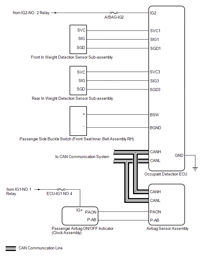 Communication Table
|
Transmitting ECU (Transmitter) |
Receiving ECU |
Signal |
Communication Method |
|---|---|---|---|
|
Airbag Sensor Assembly |
Occupant Detection ECU |
|
CAN |
|
Skid Control ECU (Brake Actuator Assembly) |
Occupant Detection ECU |
|
|
|
Occupant Detection ECU |
Airbag Sensor Assembly |
|
 Precaution
PRECAUTION
GENERAL PRECAUTION
(a) The following conditions may be interpreted as a malfunction even though
they are normal operation:
An object is placed on the passenger seat and the syst ...
 How To Proceed With Troubleshooting
CAUTION / NOTICE / HINT
HINT:
Use the following procedure to troubleshoot the occupant classification
system.
*: Use the Techstream.
PROCEDURE
1.
VEHIC ...
Other materials:
Toyota CH-R Owners Manual > Driving procedures: Parking brake
A selections can be made as desired from the following modes.
Automatic mode
The parking brake is set or released automatically according to shift lever operation.
Even when in automatic mode, the parking brake can be set and released manually.
Turns automatic mode on (while the vehicle is ...
Toyota CH-R Owners Manual > BSM (Blind Spot Monitor): Turning the BSM function/RCTA function on/off
Press ""
or ""
of the meter control switches, select
.
Press ""
or ""
of the meter control switches, select
.
Press ""
or ""
of the meter control switches, select
or
.
■The outside rear view mirror indi ...
Toyota C-HR (AX20) 2023-2026 Owner's Manual
Toyota CH-R Owners Manual
- For safety and security
- Instrument cluster
- Operation of each component
- Driving
- Interior features
- Maintenance and care
- When trouble arises
- Vehicle specifications
- For owners
Toyota CH-R Service Manual
- Introduction
- Maintenance
- Audio / Video
- Cellular Communication
- Navigation / Multi Info Display
- Park Assist / Monitoring
- Brake (front)
- Brake (rear)
- Brake Control / Dynamic Control Systems
- Brake System (other)
- Parking Brake
- Axle And Differential
- Drive Shaft / Propeller Shaft
- K114 Cvt
- 3zr-fae Battery / Charging
- Networking
- Power Distribution
- Power Assist Systems
- Steering Column
- Steering Gear / Linkage
- Alignment / Handling Diagnosis
- Front Suspension
- Rear Suspension
- Tire / Wheel
- Tire Pressure Monitoring
- Door / Hatch
- Exterior Panels / Trim
- Horn
- Lighting (ext)
- Mirror (ext)
- Window / Glass
- Wiper / Washer
- Door Lock
- Heating / Air Conditioning
- Interior Panels / Trim
- Lighting (int)
- Meter / Gauge / Display
- Mirror (int)
- Power Outlets (int)
- Pre-collision
- Seat
- Seat Belt
- Supplemental Restraint Systems
- Theft Deterrent / Keyless Entry

0.0086