Toyota CH-R Service Manual: Terminals Of Ecu
TERMINALS OF ECU
CHECK MAIN BODY ECU (MULTIPLEX NETWORK BODY ECU) AND INSTRUMENT PANEL JUNCTION BLOCK ASSEMBLY
|
*A |
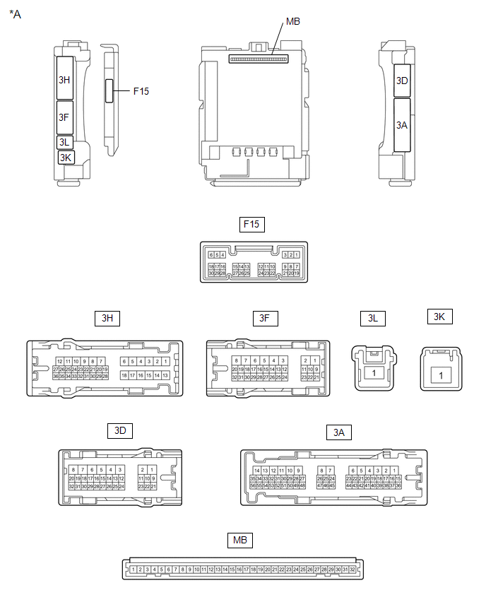
Main Body ECU (Multiplex Network Body ECU) with 1 Connector |
- |
- |
|
*A |
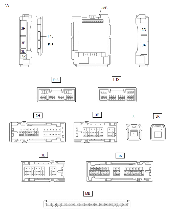
Main Body ECU (Multiplex Network Body ECU) with 2 Connectors |
- |
- |
(a) Disconnect the instrument panel junction block assembly and main body ECU (multiplex network body ECU) connectors.
Click here .gif)
(b) Reconnect the instrument panel junction block assembly connectors.
(c) Measure the resistance and voltage according to the value(s) in the table below.
HINT:
Measure the values on the wire harness side with the connector disconnected.
|
Terminal No. (Symbol) |
Wiring Color |
Terminal Description |
Condition |
Specified Condition |
|---|---|---|---|---|
|
MB-31 (BECU) - Body ground |
- |
Battery power supply |
Always |
11 to 14 V |
|
MB-32 (IG) - Body ground |
- |
Ignition power supply (IG signal) |
Ignition switch ON → off |
11 to 14 V → Below 1 V |
|
MB-30 (ACC) - Body ground |
- |
Ignition power supply (ACC signal) |
Ignition switch ACC → off |
11 to 14 V → Below 1 V |
|
MB-11 (GND1) - Body ground |
- |
Ground |
Always |
Below 1 Ω |
|
MB-2 (RCTY) - Body ground |
- |
Rear door courtesy light switch RH input |
Rear door LH closed (OFF) |
10 kΩ or higher |
|
Rear door LH open (ON) |
Below 1 Ω |
|||
|
MB-13 (LCTY) - Body ground |
- |
Rear door courtesy light switch LH input |
Rear door RH closed (OFF) |
10 kΩ or higher |
|
Rear door RH open (ON) |
Below 1 Ω |
CHECK COMBINATION METER ASSEMBLY
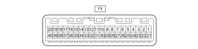
(a) Disconnect the F4 combination meter assembly connector.
(b) Measure the voltage and resistance according to the value(s) in the table below.
HINT:
Measure the values on the wire harness side with the connector disconnected.
|
Terminal No. (Symbol) |
Wiring Color |
Terminal Description |
Condition |
Specified Condition |
|---|---|---|---|---|
|
F4-40 (B) - Body ground |
SB - Body ground |
Battery power supply |
Always |
11 to 14 V |
|
F4-39 (IG+) - Body ground |
P - Body ground |
Ignition power supply |
Ignition switch off |
Below 1 V |
|
Ignition switch ON |
11 to 14 V |
|||
|
F4-21 (ET) - Body ground |
W-B - Body ground |
Ground |
Always |
Below 1 Ω |
|
F4-10 (MSD) - Body ground |
V - Body ground |
Rear LH seat belt buckle switch signal |
Rear LH seat belt fastened |
10 kΩ or higher |
|
Rear LH seat belt unfastened |
Below 1 Ω |
|||
|
F4-11 (MSTI) - Body ground |
BE - Body ground |
Rear center seat belt buckle switch signal |
Rear center seat belt fastened |
10 kΩ or higher |
|
Rear center seat belt unfastened |
Below 1 Ω |
|||
|
F4-13 (MSFM) - Body ground |
R - Body ground |
Rear RH seat belt buckle switch signal |
Rear RH seat belt fastened |
10 kΩ or higher |
|
Rear RH seat belt unfastened |
Below 1 Ω |
|||
|
F4-3 (RRMT) - Body ground |
W - Body ground |
Rear RH seat belt warning light signal |
Ignition switch ON, Rear RH seat belt unfastened within 34 seconds after closing rear door |
Below 1 V |
|
Ignition switch ON, Rear RH seat belt fastened within 34 seconds after closing rear door |
11 to 14 V |
|||
|
F4-2 (RCMT) - Body ground |
V - Body ground |
Rear center seat belt warning light signal |
Ignition switch ON, Rear center seat belt unfastened within 34 seconds after closing rear door |
Below 1 V |
|
Ignition switch ON, Rear center seat belt fastened within 34 seconds after closing rear door |
11 to 14 V |
|||
|
F4-1 (RLMT) - Body ground |
L - Body ground |
Rear LH seat belt warning light signal |
Ignition switch ON, Rear LH seat belt unfastened within 34 seconds after closing rear door |
Below 1 V |
|
Ignition switch ON, Rear LH seat belt fastened within 34 seconds after closing rear door |
11 to 14 V |
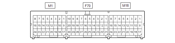
CHECK AIRBAG SENSOR ASSEMBLY
|
Terminal No. |
Terminal Symbol |
Destination |
|---|---|---|
|
M1-10 |
LBE+ |
Front seat inner belt assembly LH |
|
M1-18 |
LBE- |
Front seat inner belt assembly LH |
CHECK OCCUPANT DETECTION ECU

(a) Measure the voltage and check for pulses according to the value(s) in the table below.
|
Terminal No. (Symbol) |
Wiring Color |
Terminal Description |
Condition |
Specified Condition |
|---|---|---|---|---|
|
Y6-10 (GND) - Body ground |
W-B - Body ground |
Ground |
Always |
Below 1 V |
|
Y6-6 (IG2) - Y6-10 (GND) |
B - W-B |
Power source |
Ignition switch ON |
11 to 14 V |
|
Y6-9 (BGND) - Y6-10 (GND) |
P - W-B |
Front passenger buckle switch ground |
Always |
Below 1 V |
|
Y6-7 (BSW) - Y6-9 (BGND) |
G - P |
Front passenger buckle switch signal |
Always |
Pulse generation |
|
Y5-1 (SVC1) - Y5-5 (SGD1) |
R - G |
Front occupant classification sensor LH power supply |
Ignition switch ON |
11 to 14 V |
|
Y5-2 (SVC3) - Y5-6 (SGD3) |
GR - W |
Rear occupant classification sensor LH power supply |
Ignition switch ON |
11 to 14 V |
|
Y5-3 (SIG1) - Y5-5 (SGD1) |
P - G |
Front occupant classification sensor LH signal |
Ignition switch ON |
Pulse generation |
|
Y5-4 (SIG3) - Y5-6 (SGD3) |
SB - W |
Rear occupant classification sensor LH signal |
Ignition switch ON |
Pulse generation |
|
Y5-5 (SGD1) - Y6-10 (GND) |
G - W-B |
Front occupant classification sensor LH ground |
Always |
Below 1 V |
|
Y5-6 (SGD3) - Y6-10 (GND) |
W - W-B |
Rear occupant classification sensor LH ground |
Always |
Below 1 V |
 Diagnosis System
DIAGNOSIS SYSTEM
CHECK DLC3
(a) Check the DLC3.
Click here
INSPECT BATTERY VOLTAGE
(a) Measure the battery voltage.
Standard Voltage:
11 to 14 V
If the voltage is below 11 V, recharge or re ...
 Data List / Active Test
DATA LIST / ACTIVE TEST
DATA LIST
HINT:
Using the Techstream to read the Data List allows the values or states of switches,
sensors, actuators and other items to be read without removing any part ...
Other materials:
Toyota CH-R Service Manual > Oil Pressure Sensor: Installation
INSTALLATION
PROCEDURE
1. INSTALL OIL PRESSURE SENSOR
(a) Apply Toyota Genuine CVT fluid FE to the O-ring of the oil pressure sensor.
NOTICE:
If reusing the oil pressure sensor, check that the O-ring is not damaged.
(b) Using SST, install the oil pressure sensor to the continuously ...
Toyota CH-R Service Manual > Power Window Control System: Rear Power Window LH Auto Up / Down Function does not Operate with Rear Power
Window Switch LH
DESCRIPTION
If the manual up and down functions operate normally but the auto up and down
functions do not, the power window control system may be in fail-safe mode.
If power window initialization has not been performed, the auto up and down functions
will not operate.
Click here
WIRING ...
Toyota C-HR (AX20) 2023-2026 Owner's Manual
Toyota CH-R Owners Manual
- For safety and security
- Instrument cluster
- Operation of each component
- Driving
- Interior features
- Maintenance and care
- When trouble arises
- Vehicle specifications
- For owners
Toyota CH-R Service Manual
- Introduction
- Maintenance
- Audio / Video
- Cellular Communication
- Navigation / Multi Info Display
- Park Assist / Monitoring
- Brake (front)
- Brake (rear)
- Brake Control / Dynamic Control Systems
- Brake System (other)
- Parking Brake
- Axle And Differential
- Drive Shaft / Propeller Shaft
- K114 Cvt
- 3zr-fae Battery / Charging
- Networking
- Power Distribution
- Power Assist Systems
- Steering Column
- Steering Gear / Linkage
- Alignment / Handling Diagnosis
- Front Suspension
- Rear Suspension
- Tire / Wheel
- Tire Pressure Monitoring
- Door / Hatch
- Exterior Panels / Trim
- Horn
- Lighting (ext)
- Mirror (ext)
- Window / Glass
- Wiper / Washer
- Door Lock
- Heating / Air Conditioning
- Interior Panels / Trim
- Lighting (int)
- Meter / Gauge / Display
- Mirror (int)
- Power Outlets (int)
- Pre-collision
- Seat
- Seat Belt
- Supplemental Restraint Systems
- Theft Deterrent / Keyless Entry

0.0126