Toyota CH-R Service Manual: Front Pillar Upper Cover
Components
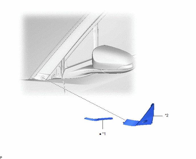
COMPONENTS
ILLUSTRATION
|
*1 |
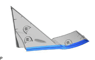
FRONT PILLAR COVER PROTECTOR |
*2 |
FRONT PILLAR UPPER COVER SUB-ASSEMBLY |
|
● |
Non-reusable part |
- |
- |
Disassembly
DISASSEMBLY
CAUTION / NOTICE / HINT
HINT:
- Use the same procedure for the RH side and LH side.
- The following procedure is for the LH side.
PROCEDURE
1. REMOVE FRONT PILLAR COVER PROTECTOR
|
(a) Remove the front pillar cover protector. |
|
Removal
REMOVAL
CAUTION / NOTICE / HINT
HINT:
- Use the same procedure for the RH side and LH side.
- The following procedure is for the LH side.
PROCEDURE
1. REMOVE FRONT PILLAR UPPER COVER SUB-ASSEMBLY
(a) Apply protective tape around the front pillar upper cover sub-assembly.
.png) |
Protective Tape |
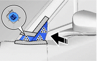
(b) Using a moulding remover B, disengage the clips to remove the front pillar upper cover sub-assembly as shown in the illustration.
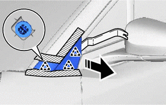
.png) |
Remove in this Direction |
Reassembly
REASSEMBLY
CAUTION / NOTICE / HINT
HINT:
- Use the same procedure for the RH side and LH side.
- The following procedure is for the LH side.
PROCEDURE
1. INSTALL FRONT PILLAR COVER PROTECTOR
HINT:
When installing the front pillar cover protector, heat the front pillar upper cover sub-assembly using a heat light.
Heating Temperature|
Item |
Temperature |
|---|---|
|
Front Pillar Upper Cover Sub-assembly |
20 to 30°C (68 to 86°F) |
CAUTION:
- Do not touch the heat light and heated parts, touching the heat light may result in burns.
- Touching heated parts for a long time may result in burns.
.png)
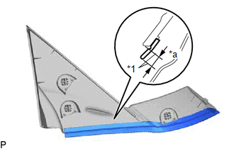
|
*a |
Heated Part |
|
*b |
Heat Light |
NOTICE:
Do not heat the front pillar upper cover sub-assembly excessively.
(a) Clean the front pillar upper cover sub-assembly surface.
(1) Using a heat light, heat the front pillar upper cover sub-assembly surface.
(2) Remove the double-sided tape from the front pillar upper cover sub-assembly.
(3) Wipe off any tape adhesive residue with cleaner.
(b) Using a heat light, heat the front pillar upper cover sub-assembly.
(c) Remove the release paper from a new front pillar cover protector.
HINT:
After removing the release paper, keep the exposed adhesive free from foreign matter.
|
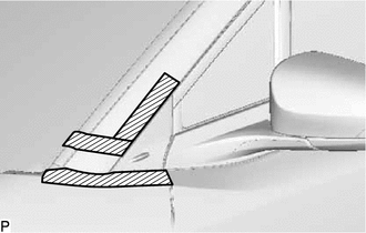
(d) Install the front pillar cover protector as shown in the illustration. HINT: Align the front pillar cover protector with the mark-off line of the front pillar upper cover sub-assembly. |
|
Installation
INSTALLATION
CAUTION / NOTICE / HINT
HINT:
- Use the same procedure for the RH side and LH side.
- The following procedure is for the LH side.
PROCEDURE
1. INSTALL FRONT PILLAR UPPER COVER SUB-ASSEMBLY
(a) Engage the clips to install the front pillar upper cover sub-assembly as shown in the illustration.
.png) |
Install in this Direction |
(b) Remove the protective tape.
 Removal
REMOVAL
CAUTION / NOTICE / HINT
The necessary procedures (adjustment, calibration, initialization or registration)
that must be performed after parts are removed and installed, or replaced during ...
 Name Plate
...
Other materials:
Toyota CH-R Service Manual > Blind Spot Monitor System: Destination Information Undefined (C1AB8)
DESCRIPTION
This DTC is stored when correct destination information is not sent from the
main body ECU (multiplex network body ECU) and destination information cannot be
confirmed after a blind spot monitor sensor has been replaced.
DTC No.
Detection Item
DTC D ...
Toyota CH-R Service Manual > Pre-collision System: Other System Malfunction (C1A63)
DESCRIPTION
The millimeter wave radar sensor receives the throttle signal from the ECM and
judges whether the driver is making an acceleration request.
When the ECM detects an electronic throttle malfunction, it informs the millimeter
wave radar sensor via CAN communication and sets DTC C1A63. ...
Toyota C-HR (AX20) 2023-2026 Owner's Manual
Toyota CH-R Owners Manual
- For safety and security
- Instrument cluster
- Operation of each component
- Driving
- Interior features
- Maintenance and care
- When trouble arises
- Vehicle specifications
- For owners
Toyota CH-R Service Manual
- Introduction
- Maintenance
- Audio / Video
- Cellular Communication
- Navigation / Multi Info Display
- Park Assist / Monitoring
- Brake (front)
- Brake (rear)
- Brake Control / Dynamic Control Systems
- Brake System (other)
- Parking Brake
- Axle And Differential
- Drive Shaft / Propeller Shaft
- K114 Cvt
- 3zr-fae Battery / Charging
- Networking
- Power Distribution
- Power Assist Systems
- Steering Column
- Steering Gear / Linkage
- Alignment / Handling Diagnosis
- Front Suspension
- Rear Suspension
- Tire / Wheel
- Tire Pressure Monitoring
- Door / Hatch
- Exterior Panels / Trim
- Horn
- Lighting (ext)
- Mirror (ext)
- Window / Glass
- Wiper / Washer
- Door Lock
- Heating / Air Conditioning
- Interior Panels / Trim
- Lighting (int)
- Meter / Gauge / Display
- Mirror (int)
- Power Outlets (int)
- Pre-collision
- Seat
- Seat Belt
- Supplemental Restraint Systems
- Theft Deterrent / Keyless Entry

0.0066