Toyota CH-R Service Manual: Removal
REMOVAL
CAUTION / NOTICE / HINT
The necessary procedures (adjustment, calibration, initialization or registration) that must be performed after parts are removed and installed, or replaced during the front door window frame moulding removal/installation are shown below.
Necessary Procedure After Parts Removed/Installed/Replaced|
Replaced Part or Performed Procedure |
Necessary Procedure |
Effect/Inoperative Function when Necessary Procedure not Performed |
Link |
|---|---|---|---|
|
Disconnect cable from negative battery terminal |
Initialize back door lock |
Power door lock control system |
|
|
Memorize steering angle neutral point |
Lane departure alert system (w/ Steering Control) |
|
|
|
Pre-collision system |
|||
|
Initialize Power Window Control System |
|
|
HINT:
- Use the same procedure for the RH side and LH side.
- The following procedure is for the LH side.
PROCEDURE
1. PRECAUTION
CAUTION:
Be sure to read Precaution thoroughly before servicing.
Click here
.gif)
.png)
NOTICE:
After turning the ignition switch off, waiting time may be required before disconnecting the cable from the negative (-) battery terminal. Therefore, make sure to read the disconnecting the cable from the negative (-) battery terminal notices before proceeding with work.
Click here
2. REMOVE FRONT DOOR BELT MOULDING ASSEMBLY
Click here
3. REMOVE FRONT DOOR OUTSIDE MOULDING SUB-ASSEMBLY
HINT:
When removing the front door outside moulding sub-assembly, heat the vehicle body and front door outside moulding sub-assembly using a heat light.
Heating Temperature|
Item |
Temperature |
|---|---|
|
Vehicle Body |
40 to 60°C (104 to 140°F) |
|
Front Door Outside Moulding Sub-assembly |
20 to 30°C (68 to 86°F) |
CAUTION:
- Do not touch the heat light and heated parts, touching the heat light may result in burns.
- Touching heated parts for a long time may result in burns.
.png)
|
*a |
Heated Part |
|
*b |
Heat Light |
NOTICE:
Do not heat the vehicle body or moulding excessively.
(a) Using a heat light, heat the front door outside moulding sub-assembly.
(b) Apply protective tape around the front door outside moulding sub-assembly as shown in the illustration.
|
*a |
Double-sided Tape |
.png) |
Remove in this Direction (1) |
.png) |
Remove in this Direction (2) |
.png) |
Protective Tape |
(c) Using a moulding remover D, disengage the clip and guide, and separate the double-sided tape and caulking sponge to remove the front door outside moulding sub-assembly as shown in the illustration.
4. DISCONNECT FRONT DOOR WEATHERSTRIP
|
(a) Using a clip remover, disengage the clips to disconnect the front door weatherstrip. |
|
5. REMOVE DOOR FRAME UPPER GARNISH
Click here
6. REMOVE FRONT DOOR GLASS RUN
Click here
7. REMOVE FRONT DOOR FRONT LOWER FRAME SUB-ASSEMBLY
Click here
8. REMOVE FRONT DOOR FIX WINDOW GLASS
Click here
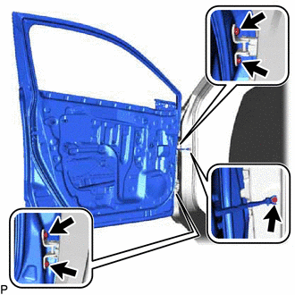
9. REMOVE FRONT DOOR UPPER WINDOW FRAME MOULDING
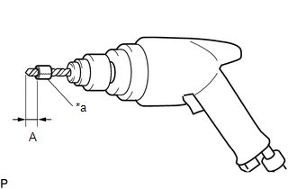
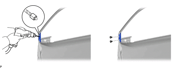
(a) Insert a 4.0 mm (0.157 in.) drill bit into a drill.
|
(b) Tape the 4.0 mm (0.157 in.) drill bit 5.0 mm (0.197 in.) from the tip as shown in the illustration. Standard Measurement:
NOTICE: Tape the 4.0 mm (0.157 in.) drill bit to prevent the drill bit from going too deep. |
|
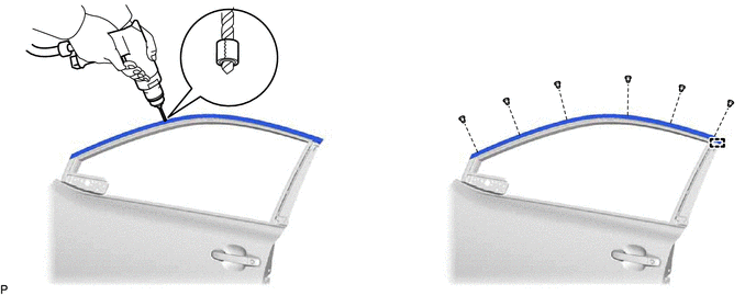
(c) Lightly press the drill bit against the rivets to drill off the rivet flanges, and remove the 6 rivets.
CAUTION:
Be careful of the drilled rivets, as they may be hot.
NOTICE:
- Pressing the drill too firmly will cause the rivet to turn and result in the rivet not being drilled through.
- Prying the rivets with the drill may damage the rivet installation holes or drill bit.
(d) Using a vacuum cleaner, remove the rivet fragments and shavings from the drilled areas.
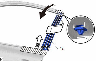
(e) Disengage the guide to remove the front door upper window frame moulding from the door frame.
10. REMOVE FRONT DOOR SCUFF PLATE
Click here
11. REMOVE COWL SIDE TRIM BOARD
Click here
12. REMOVE FRONT DOOR FRONT WINDOW FRAME MOULDING
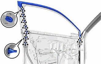
(a) Disconnect each connector.
(b) Disengage each clamp.
|
(c) Remove the 5 bolts and front door panel sub-assembly. NOTICE: To prevent damage, when removing the front door panel sub-assembly, make sure that there are enough people available to hold it securely. |
|
(d) Insert a 4.0 mm (0.157 in.) drill bit into a drill.
|
(e) Tape the 4.0 mm (0.157 in.) drill bit 5.0 mm (0.197 in.) from the tip as shown in the illustration. Standard Measurement:
NOTICE: Tape the 4.0 mm (0.157 in.) drill bit to prevent the drill bit from going too deep. |
|
(f) Lightly press the drill bit against the rivets to drill off the rivet flanges, and remove the 2 rivets and front door front window frame moulding.
CAUTION:
Be careful of the drilled rivets, as they may be hot.
NOTICE:
- Pressing the drill too firmly will cause the rivet to turn and result in the rivet not being drilled through.
- Prying the rivets with the drill may damage the rivet installation holes or drill bit.
(g) Using a vacuum cleaner, remove the rivet fragments and shavings from the drilled areas.
 Installation
INSTALLATION
CAUTION / NOTICE / HINT
HINT:
Use the same procedure for the RH side and LH side.
The following procedure is for the LH side.
PROCEDURE
1. INSTALL FRONT DOOR FRONT ...
 Front Pillar Upper Cover
Components
COMPONENTS
ILLUSTRATION
*1
FRONT PILLAR COVER PROTECTOR
*2
FRONT PILLAR UPPER COVER SUB-ASSEMBLY
●
Non-reusa ...
Other materials:
Toyota CH-R Service Manual > Rear Lower Arm: Removal
REMOVAL
CAUTION / NOTICE / HINT
The necessary procedures (adjustment, calibration, initialization, or registration)
that must be performed after parts are removed and installed, or replaced during
rear suspension arm assembly removal/installation are shown below.
Necessary Procedures After Pa ...
Toyota CH-R Service Manual > Navigation System: Illumination Circuit
DESCRIPTION
Power is supplied to the radio and display receiver assembly and steering pad
switch assembly illumination when the light control switch is in the tail or head
position.
WIRING DIAGRAM
CAUTION / NOTICE / HINT
NOTICE:
The vehicle is equipped with a Supplemental Restrain ...
Toyota C-HR (AX20) 2023-2026 Owner's Manual
Toyota CH-R Owners Manual
- For safety and security
- Instrument cluster
- Operation of each component
- Driving
- Interior features
- Maintenance and care
- When trouble arises
- Vehicle specifications
- For owners
Toyota CH-R Service Manual
- Introduction
- Maintenance
- Audio / Video
- Cellular Communication
- Navigation / Multi Info Display
- Park Assist / Monitoring
- Brake (front)
- Brake (rear)
- Brake Control / Dynamic Control Systems
- Brake System (other)
- Parking Brake
- Axle And Differential
- Drive Shaft / Propeller Shaft
- K114 Cvt
- 3zr-fae Battery / Charging
- Networking
- Power Distribution
- Power Assist Systems
- Steering Column
- Steering Gear / Linkage
- Alignment / Handling Diagnosis
- Front Suspension
- Rear Suspension
- Tire / Wheel
- Tire Pressure Monitoring
- Door / Hatch
- Exterior Panels / Trim
- Horn
- Lighting (ext)
- Mirror (ext)
- Window / Glass
- Wiper / Washer
- Door Lock
- Heating / Air Conditioning
- Interior Panels / Trim
- Lighting (int)
- Meter / Gauge / Display
- Mirror (int)
- Power Outlets (int)
- Pre-collision
- Seat
- Seat Belt
- Supplemental Restraint Systems
- Theft Deterrent / Keyless Entry

0.0102