Toyota CH-R Service Manual: Removal
REMOVAL
CAUTION / NOTICE / HINT
The necessary procedures (adjustment, calibration, initialization, or registration) that must be performed after parts are removed and installed, or replaced during the occupant detection sensor removal/installation are shown below.
Necessary Procedure After Parts Removed/Installed/Replaced|
Replaced Part or Performed Procedure |
Necessary Procedure |
Effect/Inoperative Function when Necessary Procedure not Performed |
Link |
|---|---|---|---|
|
Disconnect cable from negative battery terminal |
Initialize back door lock |
Power door lock control system |
|
|
Memorize steering angle neutral point |
Lane departure alert system (w/ Steering Control) |
|
|
|
Pre-collision system |
CAUTION:
- Some of these service operations affect the SRS airbag system. Read
the precautionary notices concerning the SRS airbag system before servicing.
.png)
Click here
.gif)
- Wear protective gloves. Sharp areas on the parts may injure your hands.
PROCEDURE
1. REMOVE FRONT SEAT ASSEMBLY
HINT:
Use the same procedure as for the driver side.
Click here
2. REMOVE FRONT SEAT INNER BELT ASSEMBLY
Click here
3. DISCONNECT SEPARATE TYPE FRONT SEATBACK COVER
HINT:
Use the same procedure as for the driver side.
Click here
4. REMOVE RECLINING HINGE OUTER COVER
HINT:
Use the same procedure as for the driver side.
Click here
5. REMOVE RECLINING ADJUSTER RELEASE HANDLE
HINT:
Use the same procedure as for the driver side.
Click here
6. REMOVE FRONT SEAT CUSHION SHIELD
Click here
7. REMOVE FRONT SEAT INNER CUSHION SHIELD
Click here
8. REMOVE SEPARATE TYPE FRONT SEATBACK ASSEMBLY
HINT:
Use the same procedure as for the driver side.
Click here
9. REMOVE SEPARATE TYPE FRONT SEAT CUSHION COVER WITH PAD
HINT:
Use the same procedure as for the driver side.
Click here
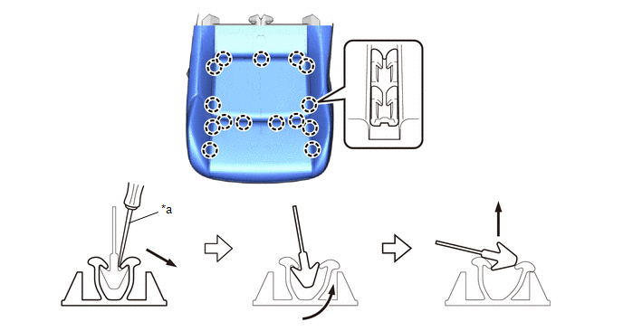
10. REMOVE OCCUPANT DETECTION SENSOR (SEPARATE TYPE FRONT SEAT CUSHION PAD)
(a) Using a screwdriver, disengage the claws to remove the occupant detection sensor (separate type front seat cushion pad) from the separate type front seat cushion cover as shown in the illustration.
|
*a |
Screwdriver |
- |
- |
 Components
COMPONENTS
ILLUSTRATION
*1
FRONT SEAT CUSHION SHIELD
*2
FRONT SEAT INNER BELT ASSEMBLY
*3
FRONT SEAT INNER CUSHION SHIELD
...
 Inspection
INSPECTION
PROCEDURE
1. INSPECT OCCUPANT DETECTION SENSOR (SEPARATE TYPE FRONT SEAT CUSHION PAD)
(a) Check the resistance.
(1) Measure the resistance according to the value(s) in the ta ...
Other materials:
Toyota CH-R Service Manual > Audio And Visual System(for Radio And Display Type): Lost Communication with Meter (B1324)
DESCRIPTION
This DTC is stored when a communication error occurs between the radio and display
receiver assembly and combination meter assembly.
DTC No.
Detection Item
DTC Detection Condition
Trouble Area
B1324
Lost Communic ...
Toyota CH-R Service Manual > Navigation System: GPS Antenna Connection Malfunction(short) (B15C0,B15C1)
DESCRIPTION
These DTCs are stored when a malfunction occurs in the navigation antenna assembly.
DTC No.
Detection Item
DTC Detection Condition
Trouble Area
B15C0
GPS Antenna Connection Malfunction(short)
Navigation ...
Toyota C-HR (AX20) 2023-2026 Owner's Manual
Toyota CH-R Owners Manual
- For safety and security
- Instrument cluster
- Operation of each component
- Driving
- Interior features
- Maintenance and care
- When trouble arises
- Vehicle specifications
- For owners
Toyota CH-R Service Manual
- Introduction
- Maintenance
- Audio / Video
- Cellular Communication
- Navigation / Multi Info Display
- Park Assist / Monitoring
- Brake (front)
- Brake (rear)
- Brake Control / Dynamic Control Systems
- Brake System (other)
- Parking Brake
- Axle And Differential
- Drive Shaft / Propeller Shaft
- K114 Cvt
- 3zr-fae Battery / Charging
- Networking
- Power Distribution
- Power Assist Systems
- Steering Column
- Steering Gear / Linkage
- Alignment / Handling Diagnosis
- Front Suspension
- Rear Suspension
- Tire / Wheel
- Tire Pressure Monitoring
- Door / Hatch
- Exterior Panels / Trim
- Horn
- Lighting (ext)
- Mirror (ext)
- Window / Glass
- Wiper / Washer
- Door Lock
- Heating / Air Conditioning
- Interior Panels / Trim
- Lighting (int)
- Meter / Gauge / Display
- Mirror (int)
- Power Outlets (int)
- Pre-collision
- Seat
- Seat Belt
- Supplemental Restraint Systems
- Theft Deterrent / Keyless Entry

0.0069