Toyota CH-R Service Manual: Installation
INSTALLATION
CAUTION / NOTICE / HINT
HINT:
- Use the same procedure for the RH side and LH side.
- The following procedure is for the LH side.
PROCEDURE
1. INSTALL FRONT LOWER COIL SPRING INSULATOR
(a) Install the front lower coil spring insulator to the front shock absorber assembly.
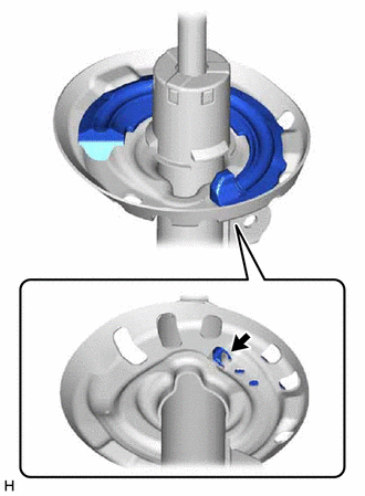
.png) |
Positioning Pin |
NOTICE:
When installing the front lower coil spring insulator, insert the positioning pin of the spring seat into the hole of the front lower coil spring insulator.
2. INSTALL FRONT SPRING BUMPER
(a) Install the front spring bumper to the front shock absorber assembly as shown in the illustration.
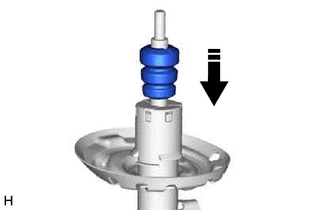
.png) |
Install in this direction |
NOTICE:
- Face the smaller diameter end of the front spring bumper downward.
- Do not apply lubricants to the front spring bumper.
- Do not apply lubricants to the front shock absorber assembly cap or rod.
- Do not clean the front spring bumper with water or solvent.
3. INSTALL FRONT COIL SPRING
|
(a) Secure SST in a vise. SST: 09727-00051 SST: 09727-30022 09727-00010 09727-00031 |
|
.png)
(b) Attach the hooks of each SST arm across the diameter of the coil spring.
CAUTION:
- Make sure that the hooks are securely attached to the coil spring.
.png)
- If a hook disengages from the coil spring, the coil spring may fly out, resulting in injury.
- Make sure that the hooks of the upper and lower SST arms are attached
to the coil spring so that the distance between the hooks is as large as
possible.
.png)
- If a hook disengages from the coil spring, the coil spring may fly out, resulting in injury.
- Make sure that the arms of SST are parallel and the number of coils
between the arms is the same on each side.
.png)
- If a hook disengages from the coil spring, the coil spring may fly out, resulting in injury.
(c) Install the stopper pins to the hooks of SST.
CAUTION:
- Make sure that the stopper pins are installed securely.
- If a hook disengages from the coil spring, the coil spring may fly out, resulting in injury.
.png)
(d) Using SST, compress the coil spring.
CAUTION:
- If the coil spring starts to bow out while using SST, stop immediately
and reattach SST correctly.
.png)
- If a hook disengages from the coil spring, the coil spring may fly out, resulting in injury.
- Do not compress the coil spring to the point where the coils touch each
other.
.png)
- If a hook disengages from the coil spring, the coil spring may fly out, resulting in injury.
- Do not use an impact wrench.
.png)
- If an impact wrench is used, the threads of SST may be damaged, or sudden compression of the coil spring may cause a hook to disengage and the coil spring to fly out, resulting in injury.
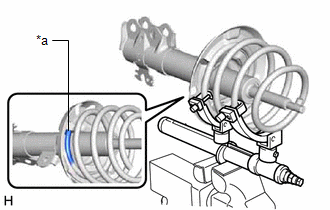
- If a stopper pin touches the coil spring while using SST, remove the
stopper pin and continue with the procedure.
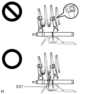
- If a stopper pin is removed, install a coil spring stopper belt as shown in the illustration.
- If a hook disengages from the coil spring, the coil spring may fly out, resulting in injury.
SST: 09727-00110
|
(e) Align the end of the front coil spring with the flange of the front lower coil spring insulator and install the front coil spring. NOTICE: Make sure to fit the end of the front coil spring that has the larger diameter into the depression of the front lower coil spring insulator. |
|
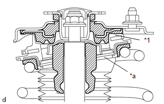
4. INSTALL FRONT SPRING SEAT SUB-ASSEMBLY WITH INSULATOR
|
(a) Install the front spring seat sub-assembly with insulator to the front shock absorber assembly. NOTICE: Make sure that the top end of the insulator (shock absorber dust cover) and the strut mounting bearing are securely attached. |
|
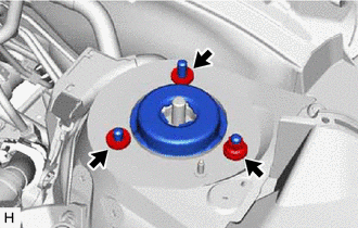
5. INSTALL FRONT SUSPENSION SUPPORT SUB-ASSEMBLY
(a) Install the front suspension support sub-assembly as shown in the illustration.
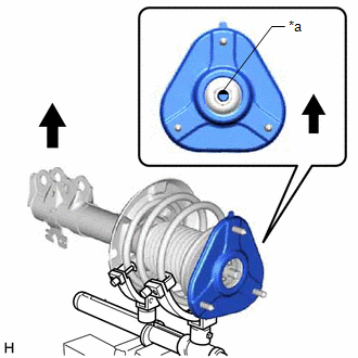
|
*a |
Slot |
|
|
Outside of the Vehicle |
NOTICE:
Check that the slot on the piston rod and the slot on the front suspension support sub-assembly are aligned.
(b) Align the protrusion of the front suspension support sub-assembly with the front shock absorber lower bracket as shown in the illustration.
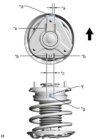
|
*a |
0°+/- 5° |
|
*b |
Guide Line of Front Suspension Support Sub-assembly |
|
*c |
Area in Which Protrusions Must Be Aligned |
|
*d |
Protrusion of Front Suspension Support Sub-assembly |
|
*e |
Front Shock Absorber Lower Bracket |
|
*f |
Protrusion of Upper Case |
|
*g |
Protrusion of Lower Case |
|
|
Outside of the Vehicle |
NOTICE:
Make sure to install the front suspension support sub-assembly so that the protrusion of the front suspension support sub-assembly is aligned within +/- 5° of the center of the front shock absorber lower bracket.
(c) Align the protrusions of the upper case and lower case of the strut mounting bearing as shown in the illustration.
NOTICE:
Make sure to install the front spring seat sub-assembly with insulator so that the protrusion of the upper case of the strut mounting bearing overlaps with the protrusion of the lower case within the guide lines of the front suspension support sub-assembly.
6. INSTALL COLLAR
(a) Install the collar to the front shock absorber assembly.
7. TEMPORARILY TIGHTEN FRONT SUPPORT TO FRONT SHOCK ABSORBER NUT
(a) Temporarily tighten a new front support to front shock absorber nut.
(b) Remove SST from the front coil spring.
NOTICE:
Do not use an impact wrench. It will damage SST.
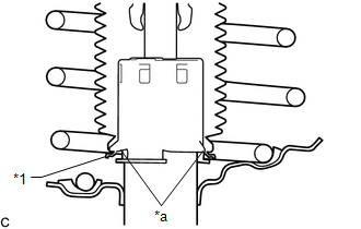
8. CONNECT FRONT SPRING SEAT SUB-ASSEMBLY WITH INSULATOR
|
(a) Connect the end of the insulator of the front spring seat sub-assembly with insulator with the claws of the front shock absorber assembly. NOTICE:
|
|
9. INSTALL FRONT SHOCK ABSORBER WITH COIL SPRING
|
(a) Install the front shock absorber with coil spring (upper side) with the nut and 2 spacers. Torque: 50 N·m {510 kgf·cm, 37 ft·lbf} |
|
|
(b) Temporarily install the 2 nuts to the front shock absorber assembly. |
|
(c) Install the front shock absorber with coil spring (lower side) to the steering knuckle with the 2 bolts and 2 nuts.
Torque:
270 N·m {2753 kgf·cm, 199 ft·lbf}
NOTICE:
- When installing the nuts, keep the bolts from rotating.
- Do not apply lubricants to the steering knuckle and shock absorber contact surfaces.
HINT:
The bolts can be installed in either direction, however, make sure that they are both installed in the same direction.
10. INSTALL FRONT SPEED SENSOR
|
(a) Engage the 2 hooks of front speed sensor to the front shock absorber assembly. NOTICE: Do not twist the front speed sensor when installing it. |
|
.png)
|
(b) Install the front speed sensor and front flexible hose to the front shock absorber assembly with the bolt. Torque: 29 N·m {296 kgf·cm, 21 ft·lbf} |
|
.png)
(c) Engage the clamp.
11. INSTALL FRONT STABILIZER LINK ASSEMBLY
(a) Install the front stabilizer link assembly to the front shock absorber assembly with the nut.
Torque:
74 N·m {755 kgf·cm, 55 ft·lbf}
HINT:
If the ball joint turns together with the nut, use a 6 mm hexagon socket wrench to hold the stud bolt.
12. FULLY TIGHTEN FRONT SUPPORT TO FRONT SHOCK ABSORBER NUT
(a) Fully tighten the front support to front shock absorber nut.
Torque:
47 N·m {479 kgf·cm, 35 ft·lbf}
NOTICE:
Perform this step only when the front shock absorber with coil spring has been disassembled.
|
(b) Remove the 2 nuts from the front shock absorber assembly. |
|
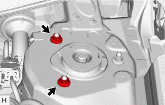
13. INSTALL FRONT SUSPENSION SUPPORT DUST COVER
(a) Install the front suspension support dust cover.
14. INSTALL OUTER COWL TOP PANEL SUB-ASSEMBLY
(a) Install the outer cowl top panel sub-assembly with the 8 bolts and 4 nuts.
Torque:
Bolt :
12 N·m {122 kgf·cm, 9 ft·lbf}
Nut :
50 N·m {510 kgf·cm, 37 ft·lbf}
(b) Engage the 2 clamps to install the wire harness to the outer cowl top panel sub-assembly.
(c) w/ Windshield Deicer:
(1) Engage the 2 clamps to install the wire harness to the outer cowl top panel sub-assembly.
(2) Connect the connector.
15. INSTALL COWL BODY MOUNTING REINFORCEMENT RH
(a) Install the cowl body mounting reinforcement RH to the vehicle body with the 2 bolts.
Torque:
12 N·m {122 kgf·cm, 9 ft·lbf}
16. INSTALL COWL BODY MOUNTING REINFORCEMENT LH
(a) Install the cowl body mounting reinforcement LH to the vehicle body with the bolt.
Torque:
12 N·m {122 kgf·cm, 9 ft·lbf}
17. INSTALL WATER GUARD PLATE LH
(a) Engage the claw to install the water guard plate LH to the outer cowl top panel sub-assembly.
18. INSTALL NO. 1 HEATER AIR DUCT SPLASH SHIELD SEAL
(a) Engage the claw to install the No. 1 heater air duct splash shield seal to the outer cowl top panel sub-assembly.
19. INSTALL WINDSHIELD WIPER MOTOR AND LINK ASSEMBLY
Click here
.gif)
20. INSTALL FRONT WHEEL
Click here
21. STABILIZE SUSPENSION
(a) Lower the vehicle.
(b) Bounce the vehicle up and down several times to stabilize the suspension.
22. INSPECT AND ADJUST FRONT WHEEL ALIGNMENT
Click here
23. PERFORM INITIALIZATION (w/ Height Control Sensor)
Click here
 Inspection
INSPECTION
PROCEDURE
1. INSPECT FRONT SHOCK ABSORBER ASSEMBLY
(a) Compress and extend the front shock absorber assembly rod 4 times or more.
Standard:
When compressed and extended at a constant ...
 Disposal
DISPOSAL
PROCEDURE
1. DISPOSE OF FRONT SHOCK ABSORBER ASSEMBLY
CAUTION:
Always use a cloth to prevent shards of metal flying about due to the
release of pressurized gas.
Always wea ...
Other materials:
Toyota CH-R Service Manual > Vehicle Stability Control System: Brake Pedal Load Sensing Switch OFF Stuck Malfunction (C1430,C1431)
DESCRIPTION
The brake pedal load sensing switch turns on when the brake pedal is depressed
with a force exceeding a predetermined level.
The skid control ECU uses this circuit to detect if the brake pedal is depressed
or not.
DTC No.
Detection Item
DTC Detecti ...
Toyota CH-R Service Manual > Audio And Visual System(for Radio And Display Type): Portable Player cannot be Registered
CAUTION / NOTICE / HINT
HINT:
Some versions of "Bluetooth" compatible audio players may not function, or the
functions may be limited using the radio and display receiver assembly, even if
the portable audio player itself can play files.
Click here
PROCEDURE
1.
...
Toyota C-HR (AX20) 2023-2026 Owner's Manual
Toyota CH-R Owners Manual
- For safety and security
- Instrument cluster
- Operation of each component
- Driving
- Interior features
- Maintenance and care
- When trouble arises
- Vehicle specifications
- For owners
Toyota CH-R Service Manual
- Introduction
- Maintenance
- Audio / Video
- Cellular Communication
- Navigation / Multi Info Display
- Park Assist / Monitoring
- Brake (front)
- Brake (rear)
- Brake Control / Dynamic Control Systems
- Brake System (other)
- Parking Brake
- Axle And Differential
- Drive Shaft / Propeller Shaft
- K114 Cvt
- 3zr-fae Battery / Charging
- Networking
- Power Distribution
- Power Assist Systems
- Steering Column
- Steering Gear / Linkage
- Alignment / Handling Diagnosis
- Front Suspension
- Rear Suspension
- Tire / Wheel
- Tire Pressure Monitoring
- Door / Hatch
- Exterior Panels / Trim
- Horn
- Lighting (ext)
- Mirror (ext)
- Window / Glass
- Wiper / Washer
- Door Lock
- Heating / Air Conditioning
- Interior Panels / Trim
- Lighting (int)
- Meter / Gauge / Display
- Mirror (int)
- Power Outlets (int)
- Pre-collision
- Seat
- Seat Belt
- Supplemental Restraint Systems
- Theft Deterrent / Keyless Entry

0.0141